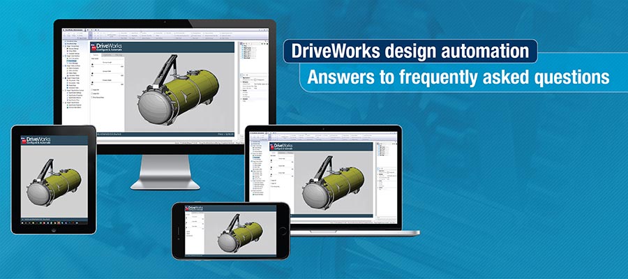
As CAD automation becomes an integral part of the manufacturing industry, our design automation experts offer answers to frequently asked questions about SolidWorks CAD automation using DriveWorks.
CAD platforms have enhanced drafting techniques by eliminating erroneous manual drafting, the need to preserve paper drawings, time-consuming revisions, and much more. They have enabled seamless design communication across teams and easy referencing for future designs. As a result, a sharp rise in designers’ and manufacturers’ productivity along with drawing quality is seen.
One of the biggest challenges of standalone 3D CAD modeling platforms is that they are time-consuming. Designers end up spending a significant amount of time in repetitive drafting work when designs are customized and drawing accuracy is compromised.
DriveWorks – a brilliant design automation and customization software that works in tandem with SolidWorks holds the key to these challenges.
DriveWorks uses logical rules to automate repetitive modeling work and customize designs at accelerated speed as well as accuracy. Design automation with DriveWorks implementation has enabled designers to reduce engineering lead time from several days to a few minutes, and achieve approximately 70% faster design cycles and 99% drawing quality.
Despite the said benefits, design automation still remains a new concept for many in the industry. So without much ado, we answer the top questions related to DriveWorks automation, adoption and implementation.
Design automation can reduce design development costs by 40%
Talk to our automation specialists »Master models and company-specific standard BoM templates are generated in SolidWorks and Word/PDF/Excel templates outside of the DriveWorks. Once you have the template ready and captured in DriveWorks, all the details and custom properties are then linked with DriveWorks for customization.
To customize master models and BoM templates:
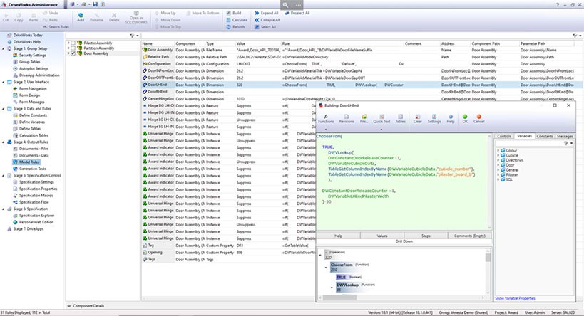
These rules drive the changes in models/drawings and BoMs. When the user inputs the values, the variable interacts with the template for BoM and drawings to deliver resultant files as per the layout captured and specified earlier.
To create custom quotes, customers (or the sales team) specify product specifications through a series of user-forms. These forms implement logical rules to modify the master model and generate user-specific customized product.
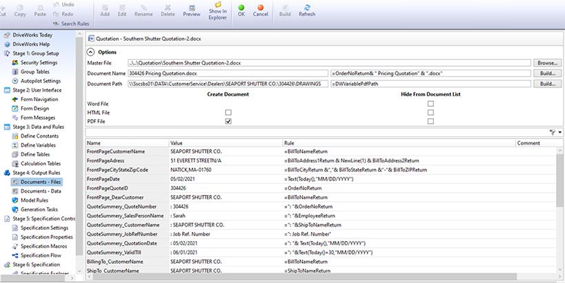
Once the order is confirmed, customized models are saved to a specified location and relevant documents are generated. The aggregated data of product specification and customer details is then exported to a table in MS Excel (or MS Word/PDF document as specified by the client) and is updated when the table is modified.
Below are some points to note about the order-approval process:
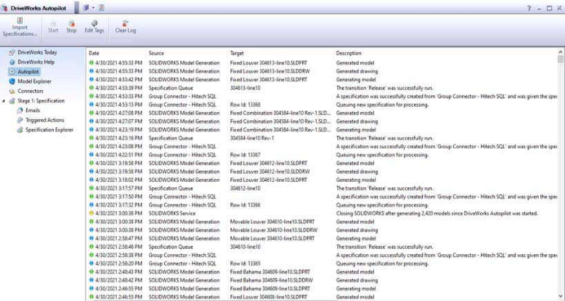 Source: DriveWorks
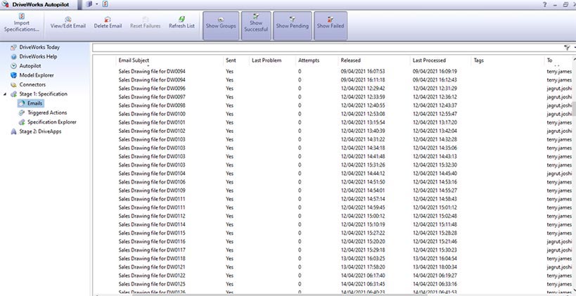 Source: DriveWorks
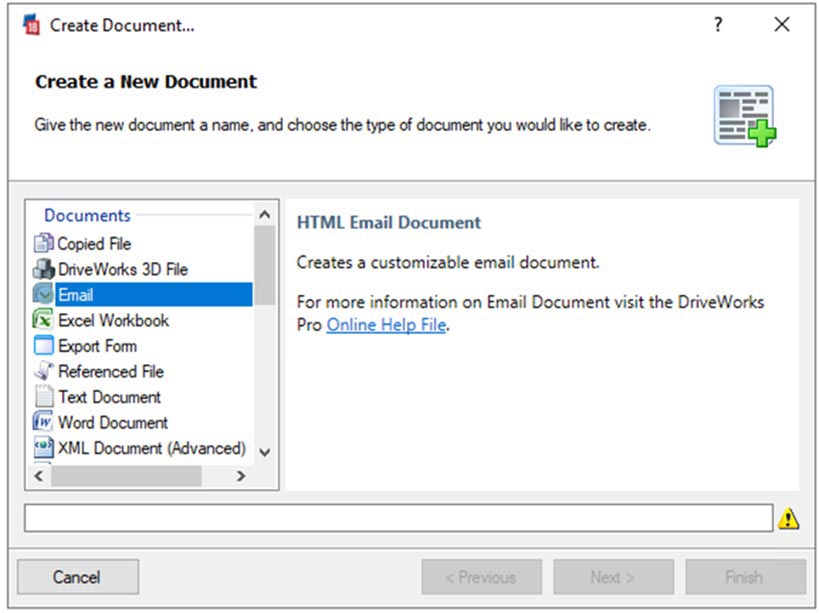
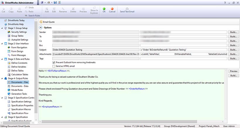
The screen will display “Email Editor” showing parameters like cc/bcc/subject etc. and an email body area where you can type the content of the email.
DriveWorks has in-built forms through which you can configure the properties, design features, look and feel of the product, etc.
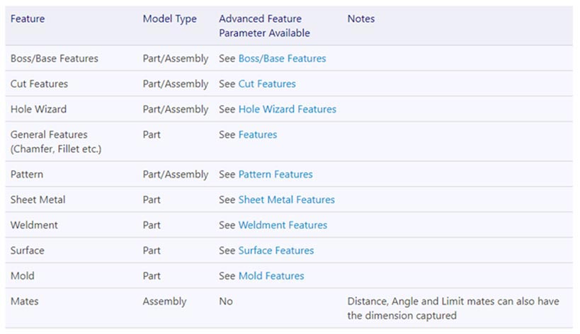
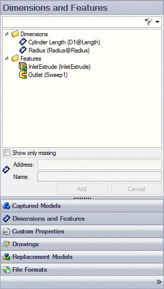
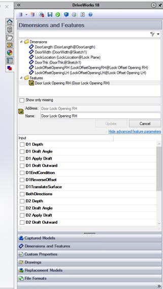
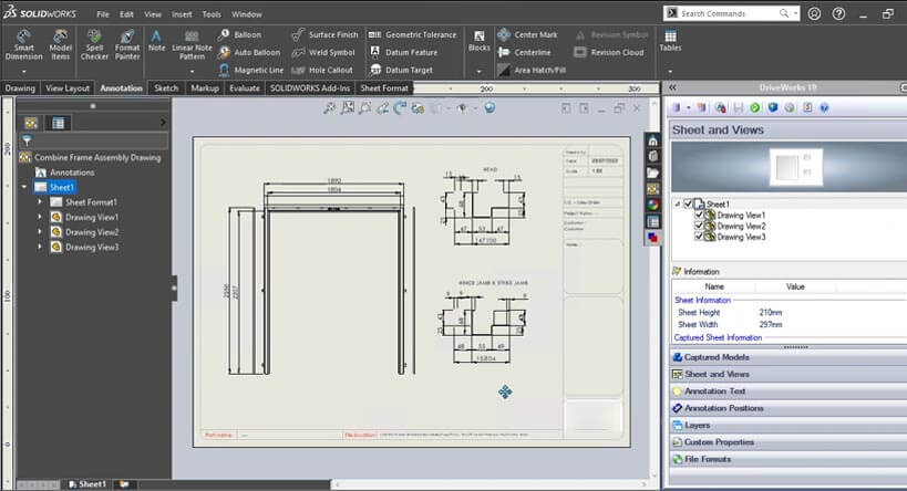
To control and modify the drawings, open the master model assembly in DriveWorks. It will display a dialogue box to specify which properties are to be automated along with the options such as dimensions, color, custom properties, etc. In the case of a sheet metal assembly, the dialogue box offers advanced features like sheet metal patterns etc.
For example, when you have to automate the “Extrude” operation, it can be done either unidirectional or bi-directional. For bi-directional extrude, the user needs to specify the direction and the length of extrude on either side: left side, right side, or mid-plane. Your automation engineer will tell you how you should proceed depending upon the product and the application of models downstream.
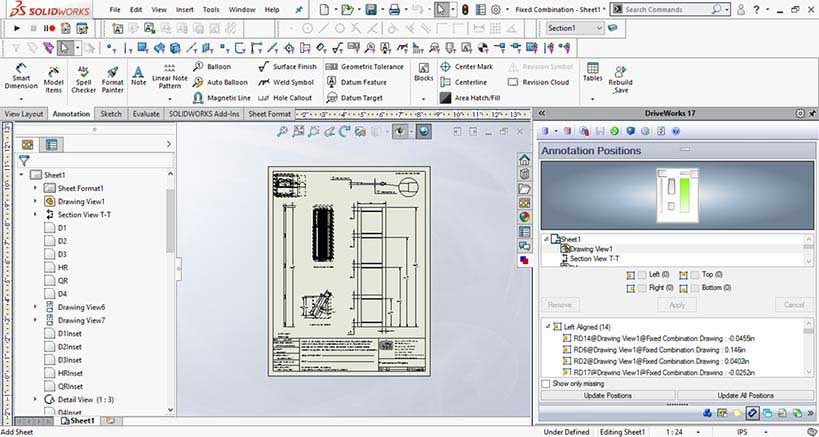
Drawings primarily consist of a range of dimensions and annotations for special notes, views in a standard template with BoM tables etc. For example, for a door assembly, you can define how the length, breadth, and height are oriented and placed in 3D space with respect to the reference planes.
DriveWorks allows you to select the drawings and models you want to modify by setting up the rules. Once you have the models and componentry that you want to modify, you can set upper and lower limits for dimensions using the rules task in the command bar in project designer. You can also capture views and other dimensions from the drawing files and create rules for them.
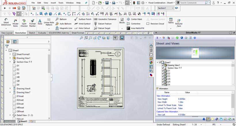
The short answer is negative. This is because both, DriveWorks Autopilot and SolidWorks have different but interlinked functions to perform. When the automation engineer releases customized models from DriveWorks, the request is entered in a queue. Autopilot will observe the queue and create models in SolidWorks as per the Rule Builder’s variables, while the actual customization happens in SolidWorks only.
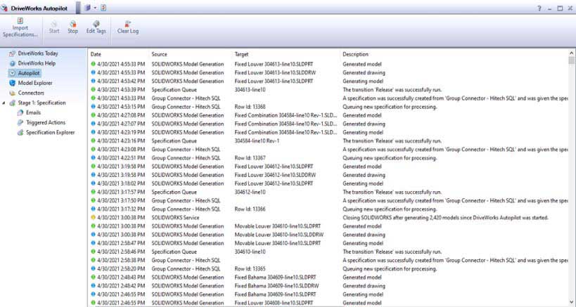
Thus, the function of Autopilot mode in DriveWorks is to trigger the queue while that of SolidWorks is to generate the custom parametric models as per the inputs. In some, one-off, 3D scenarios where every design feature is already configured in DriveWorks, there is no need of Autopilot or SolidWorks.
Yes, macros can be developed to automate many small and complex tasks while modeling in CAD software like SolidWorks. Macros are scripts that store a series of commands in a sequential way and execute the same when they are run.
Design automation using macros, allows users to avoid doing by hand many repetitive tasks required to create a 3D model. This is extremely useful where modeling of a single part of a multi-part final component is involved.
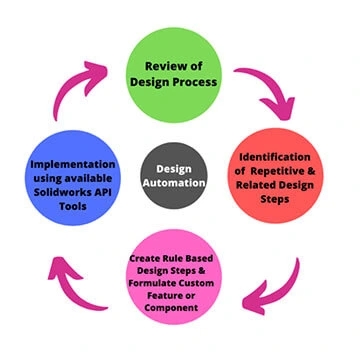
SolidWorks lets a user create a macro within and outside of its environment. While creating a new macro, one can program the macro directly using Microsoft Visual Basic via macro editing applications. Visual Basic for Applications (VBA) is the engine that records, runs, or edits macros in SolidWorks. It allows third-party integration to automate the modeling process through APIs and design automation platforms like DriveWorks.
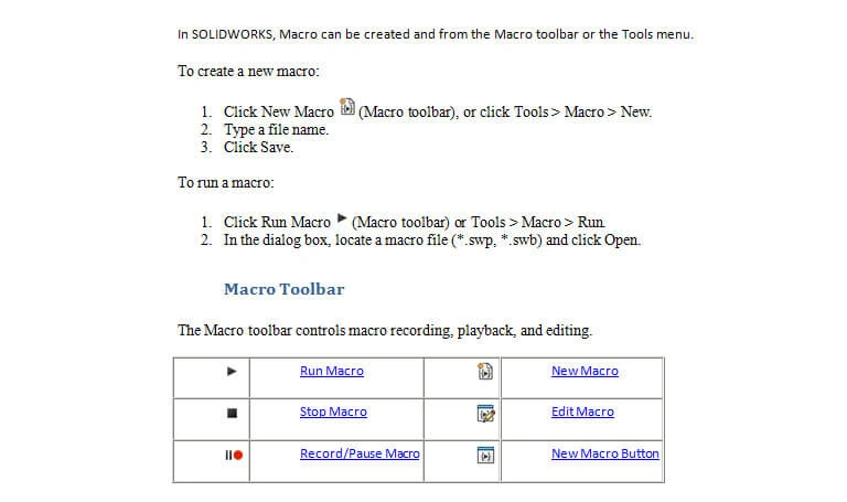
Design engineers are required to calculate part dimensions to address functional or load criterion. Usually, they use excel spreadsheets or other engineering applications to perform these design calculations. They fetch dimensions directly from data sheets to auto-create a 3D model via parametric rules. The parametric rules are built by integrating macros and APIs with CAD.
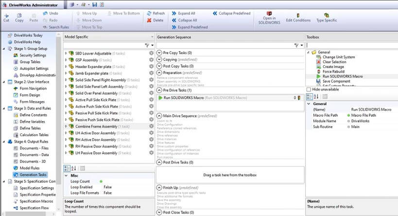
Using DriveWorks, one can make models with more accurate product visualization as compared to standalone CAD. Using Appearances in DriveWorks, 3D models can match any given 3D scene.
Input Forms are essential to embed logic via the rule builder. To set up a new design automation project, DriveWorks has a three-step process in project designer:
The first step is to create new forms and navigation. For creating any basic user interface and automation programs/ projects in DriveWorks, forms are necessary. These forms are created using the “New Form” button on the command bar.
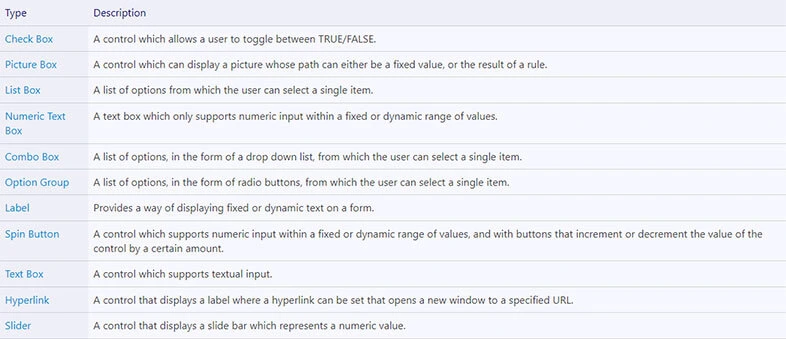
The form controls that are supported by DriveWorks Solo are:
Forms must be correctly navigated using Form Navigation. It helps in quick creation of multiple input forms. Linking a decision to the navigation has three possibilities:
The second step is to create a rule using the rule builder for each form created for user interface. It is done through the rule builder by using constants, variables, and tables.
Rules can be expressed as a simple action, complex calculations, or a series of instructions. With DriveWorks, the rules engine helps automate tasks in the best possible way. In DriveWorks, rules can be built using equations, sums and logical expressions, or business logic.
DriveWorks attaches color codes to various items it recognizes.

The third step is to set up data output formats, data values and model formats using output rules. There can be multiple options for generating 3D model and documents like quotes, bill of materials, covering letters etc.

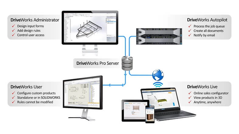
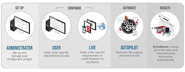
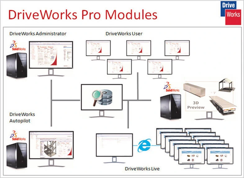
DriveWorks Pro has 4 software modules. And with this modularity of DriveWorks Pro, building solutions in response to changing needs becomes convenient and easy.
A DriveWorks Pro installation usually includes DriveWorks Administrator, DriveWorks Autopilot, DriveWorks User and DriveWorks Live, all accessing the same DriveWorks data.
First start with DriveWorks Administrator and then keep adding functionalities and modules, as and when needed. Additional modules are also available based on the requirements and complexity of design automation projects.
DriveWorks Pro Administrator
DriveWorks Administrator is a basic module of DriveWorks Pro that allows you to create design automation projects and configurations locally. It uses SOLIDWORKS and connects with external data sources that allow you to create custom designs and documentations.
DriveWorks Pro Autopilot
DriveWorks Autopilot is a module of DriveWorks Pro that runs automatically to:
DriveWorks Pro User
With DriveWorks Pro User, all engineers, sales teams and non-technical users within your local network can run defined design automation projects. They can configure custom products and create sales and manufacturing documentation automatically. However, they cannot edit rules and have some restrictions on making changes.
DriveWorks Pro Live
DriveWorks Pro Live is essential to go online with a sales product configurator. It enables sales teams, distributors, dealers, and customers to easily configure and view CTO products in 3D on any device through their web browser.
3D Viewer
With the DriveWorks 3D Viewer you can view DriveWorks 3D files (.drive3d) and many other 3D file formats. These files can also be viewed inside the 3D Viewer and then saved as DriveWorks 3D files (.drive3d).
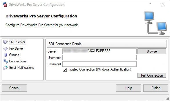
DriveWorks Pro Server
DriveWorks Pro Server comes as a free tool with DriveWorks.
It is used to manage the Shared Groups created by the DriveWorks Administrator and accessed by all DriveWorks Pro modules.
DriveWorks CPQ DriveApp
The DriveWorks CPQ DriveApp helps manufacturers quickly leverage the gains of online selling by using the Configure Price Quote. It helps in creating and managing quotes and ordering for CTO offerings.
DriveWorks Data Management
The Data Management tool is used to manage data stored in DriveWorks that includes:
To run DriveWorks with basic modules of DriveWorks Pro and additional modules, the minimum requirements are as follows:
Workstations should have minimum Intel or AMD CPU with SSE2 support, 8 GB RAM, 300 MB of hard disk space for installation. It must have graphics card approved by DirectX 11 and supported by SolidWorks. One also need a 100 MB or faster network card, 64-bit Windows operating systems 8.1 and onwards.
High-end modules of DriveWorks need a data server with Windows OS, Microsoft SQL with .NET framework and DirectX components. For the cloud, Microsoft Azure is used. For web browsers, it uses Microsoft Edge. A web browser is required only when running a personal web edition through DriveWorks Administrator, or when accessing or running a project over the internet through DriveWorks Live.
DriveWorks has its own database in SQL server/Express and can also save group tables on the system hard drive. All project level calculations are stored in project files. These files are in turn saved on the hard disk. Alongside, you also have DriveApp that offers connecting to this SQL database.
The advanced module of the CPQ DriveApp allows adding and managing data to create custom quotations and orders.
With the DriveApp, you have the power to store data for:
All the above data can be used for creating custom quotes and orders inside the DriveWorks CPQ DriveApp.
The Rule Builder in DriveWorks helps you manage the captured features, dimensions, custom properties, and much more. It uses logic statements, constants, variables, and excel-like functions to perform the necessary tasks.
DriveWorks permits addressing five major functionalities through the rule builder.
Writing rules
Using arithmetic, string, formatting, boolean operations, and functions
Any rule involves a function to first evaluate conditions and then return an answer. But it can also be a number or text of a fixed or static value.
Examples

The Functions button in the rule builder is found on the left of the command bar.

Clicking the Functions button will open the Functions dialog.
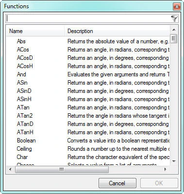

Rule Builder, allows to create, validate, and implement the logics of design automation projects.
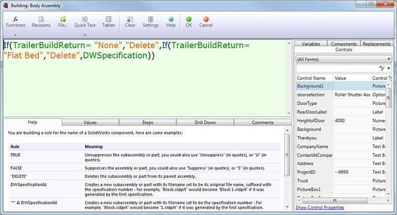
The rules builder is divided into four sections:
Extract Variable function allows variables to be created directly from the Rule Builder.
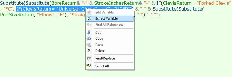
A new variable can be created by extracting anything entered in the rule editor.
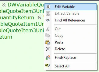
With the Edit Variable function, you can modify variables directly from the Rule Builder.
Rule Builder Settings allow users to apply custom settings to the Rule Editor. Using this, the user can change the default font, font size and colors for display rules and associated display items.
Customer involvement during the design stage has risen over the past few years. It has increased design customization as every customer has personalized need. The manufacturer who can offer customized products faster gets the highest market share. And CAD automation allows you to deliver exactly this by accelerating engineering lead time and almost zero errors in manufacturing–ready drawings.
While there are different automation tools available in the market, all of them have a primary goal of enabling designers and manufacturers to get to the market faster and with improvised design efficiencies. Find out the tool that suits your enterprise’s goals and is compatible with your primary CAD system. Set your design team out to explore and leverage the capabilities of CAD automation!
Implement DriveWorks with authorized partners
Contact us today »You may also like
From 2D to 3D: Why Architects are Switching to BIM Modeling
10 Essential Best Practices for BIM in MEP Engineering
How 3D Scan to Revit Can Solve As-Built Modeling Challenges
DXF Files in SolidWorks: How to Import and Export Them