Sheet Metal Bending in SolidWorks: The Ultimate Guide [2025]
Published on July 16th, 2024
Updated on January 10th, 2025
Precision in design and complexity of calculation are two crucial factors for optimizing sheet metal bending designs. Using the right SolidWorks sheet metal tools streamlines fabrication workflows, setting new standards in bend design accuracy and efficiency.
Precision of design, dimension, force, and other calculations is pivotal to maximizing efficiency of sheet metal fabrication and bending. For this reason, SolidWorks sheet metal tools have become the design software of choice for fabricators and manufacturers. However, sheet metal bending in SolidWorks requires a solid grasp of sheet metal design principles and an awareness of the manufacturing process.
SolidWorks 2024 offers specialized tools and advanced features like lofted bends and new enhancements for more efficient fabrication workflows. Other in-built tools like K-Factor, bend allowance, and bend deduction calculations; designers can accurately predict the outcome of their designs before moving to production. Furthermore, the inclusion of sheet metal bend detail callouts on drawings ensures clear communication between designers, engineers, and fabricators, minimizing errors and rework.
This guide explores the essential aspects of sheet metal bending in SolidWorks, including creating base flanges, adding, and editing flanges, calculating sheet metal parameters, and utilizing the latest updates.
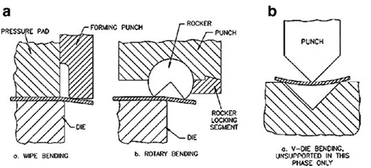
There are several types of bends that can be performed on sheet metal, each with its own applications and characteristics:
V-bending: The most common type of bending, in which the sheet is pressed into a V-shaped die.
Edge bending: Involves bending the sheet over a straight edge.
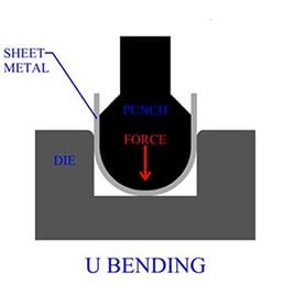
U-bending: Like V-bending but creates a U-shaped profile.
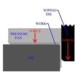
Wipe bending: The sheet is bent by being pressed against a die with a wiping motion.
Rotary bending: The sheet is bent around a rotating cylinder.
Key Parameters in Sheet Metal Bending
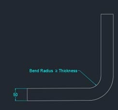
Bend Radius (R): The radius of the inner surface of the bend. It is a critical factor, as it affects the amount of spring back and the potential for material cracking. Thicker materials and those with higher tensile strength typically require larger bend radii.
Bend Angle: The angle to which the sheet metal is bent. Precise control of the bend angle is crucial for the functionality and aesthetics of the final product.
K-factor: A value that represents the location of the neutral axis in the material, which is the axis within the material where no tension or compression occurs during bending. The K-factor is used to calculate the sheet metal bend allowance and is influenced by material properties and the bend radius.
Material Thickness: Thicker materials require more force to bend and are more susceptible to spring back, which is the tendency of the metal to return to its original shape after bending.
Tensile Strength: Materials with higher tensile strength are more resistant to deformation, requiring greater force to achieve the same bend as softer materials.
Elongation: The ability of the material to stretch without breaking. Materials with higher elongation are more ductile and can be bent to tighter radii without cracking.
How to Calculate Sheet Metal Bend Allowance and Bend Deduction
To accurately predict the final dimensions of a bent part, here are the formulas used for sheet metal bend allowance and bend deduction:
Bend Allowance (BA): The length of the neutral axis between the bend lines, or the arc length of the bend.
The calculation:
Bend Allowance = π/180 x (R + K x T) x A
R – bend radius
K – k-factor
T- material thickness
A – bend angle in degrees
Bend Deduction (BD): The amount of material removed from the total length of the flat sheet to achieve the desired dimensions after bending. It is derived from the bend allowance and the bend angles.
The calculation:
Bend Deduction = 2 x (R + T) x tan (A/2) – BA
R – bend radius
T- material thickness
A – bend angle in degrees
BA – Bend Allowance
These calculations are essential for creating accurate flat patterns that, when bent, will result in the correct final dimensions and angles for the sheet metal part. The precision of these calculations is critical, as even small errors can lead to parts that do not fit or function as intended.
Get accurate bend allowance for your unique sheet metal designs.
Sheet metal bending can benefit greatly from the accuracy and repeatability afforded by 3D CAD software. 3D CAD modeling for sheet metal design allows creating complex and customized designs that were once difficult or impossible to achieve, enabling more innovative applications across industries such as automotive, aerospace, and construction. 3D CAD tools not only accelerate the production cycle but also enhance the overall quality and functionality of the final products.
In the context of SolidWorks, sheet metal bending design is a comprehensive process that involves various tools and techniques to create precise and accurate sheet metal parts. The 2024 updates to SolidWorks have introduced several new features and enhancements that streamline the sheet metal design process, making it more efficient and user friendly.
Setting Up SolidWorks for Sheet Metal Bending
To prepare your SolidWorks environment for sheet metal bending, you need to set up the sheet metal parameters that will be used across your designs. This includes specifying the material thickness, bend radius, and default K-factor, which are essential for accurate bending operations.
Setting up Sheet Metal Parameters in SolidWorks
Material Thickness: This is the starting point for any sheet metal component. You can set the default material thickness when you create a new sheet metal part using the “Base Flange/Tab” feature.
Bend Radius: The default bend radius can be set in the Sheet Metal feature by editing the “Sheet-Metal” feature in the FeatureManager design tree.It is important to choose a value of bend radius that is suitable for the material and thickness you are using.
Default K-Factor: The K-factor is a ratio that represents the location of the neutral axis with respect to the thickness of the sheet metal part. You can set a default K-factor in SolidWorks by accessing the “Sheet Metal Gauges” list and selecting the appropriate material gauge table. SolidWorks also provides a K-factor bend table in Microsoft Excel format that can be used to specify different values for the K-factor in different configurations.
Tools and Features in SolidWorks 2024 for Sheet Metal Design
All versions of SolidWorks, including SolidWorks 2024, provide a dedicated “Sheet Metal” toolbar that contains all the tools necessary for sheet metal design:
Base Flange/Tab: This is the primary feature used to create the initial sheet metal part. It defines the material thickness and bend radius.
Edge Flange: Allows you to add flanges to the edges of the sheet metal part. You can adjust the flange parameters, such as angle, length, and bend radius.
Miter Flange: Used to create a series of flanges along a series of edges, typically at the corners of the part.
Bend Table: A feature that allows you to use a table to define bend allowances or bend deductions for different bend angles and radii, ensuring accurate bending.
Best Practices for Sheet Metal Bending in SolidWorks
When designing sheet metal parts in SolidWorks, it’s important to follow best practices to ensure that the parts can be manufactured accurately and efficiently. If reducing cost is your primary concern, check out our blog on best practices for sheet metal modeling to reduce fabrication cost.
Sketching and Modeling Sheet Metal Parts in SolidWorks
Start with the Base Flange/Tab: Begin your design by creating the base flange, which sets the foundation for your part
Use the Correct Material and Thickness: Always select the correct material and thickness for your part, as this will affect the bend radius and the K-factor.
Design with Manufacturability in Mind: Consider the tools and processes that will be used to fabricate the part. Avoid complex bends that may be difficult to manufacture.
Applying Bend Features in SolidWorks
Creating Flanges: Use the “Edge Flange” tool to add flanges to your part. You can control the flange parameters directly in PropertyManager.
Creating Bends: Use the “Sketched Bend” feature to add bends to your part. You can sketch the line where the bend will occur and specify the bend direction and angle.
Using the Bend Table: For accurate bending, use the “Bend Table” feature to define the bend allowance or bend deduction based on the material, thickness, and bend radius. This ensures that the flat pattern dimensions are correct when the part is bent.
By following these guidelines and utilizing the right design tools, you can create sheet metal parts that are optimized for bending and fabrication. Remember to always verify your designs with the actual manufacturing capabilities and adjust your parameters accordingly to match the tools and processes used by your fabricator.
Hire an expert team of CAD design engineers to enhance your sheet metal designs.
Top 11 Sheet Metal Bending Techniques in SolidWorks
Creating Base Flanges and Adding Flanges
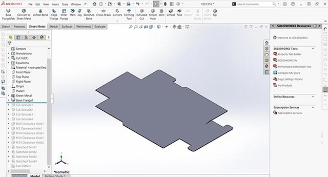
The foundation of any sheet metal part in SolidWorks is the base flange. To start, sketch an open profile and use the base flange feature to create the thin feature and the bends. This process is straightforward, thanks to SolidWorks’ intuitive interface and sheet metal design features.
Adding flanges to your sheet metal part is a critical step in creating the final shape of your part. SolidWorks allows for the addition of edge flanges or sketched bends, making it relatively simple to design for sheet metal bending. The software calculates the correct size of your sheet metal flat pattern based on bend allowance calculations, which can be specified using parameters such as K-factor, bend deduction, or even a bend table.
Calculating Sheet Metal Parameters
SolidWorks automates much of the bend allowance math, allowing you to specify parameters like K-factor, bend deduction, or use a bend table. This automation ensures that your sheet metal parts are designed with precision, considering the unique characteristics of each material type, material thickness, and bend angle.
Utilizing SolidWorks 2024 Updates
SolidWorks 2024 introduces several exciting features and enhancements to the sheet metal design process:
Tab and Slot Tool Enhancements: When adding a part with an existing Tab and Slot feature to an assembly, you can now propagate the matching slots to adjacent components. This feature simplifies the assembly process and ensures alignment.
Stamp Feature: A new tool for adding indentations in a sheet metal part without needing to create a forming tool. Any closed sketch can be used to create a stamp feature, allowing for more design flexibility.
Rip Tool Enhancements: The Rip tool now offers options for cylindrical or conical bodies, helping to create gaps in these parts with just an edge and a point in a sketch. This enhancement simplifies the process of turning cylindrical or conical shapes into sheet metal parts.
Create sheet metal designs in SolidWorks 2024 with our upgraded license and team
Designing parts with non-standard bends, such as curved or irregular shapes, presents a unique set of challenges like predicting material’s behavior during the bending process. There are several factors, like bend allowance, spring back, and the material’s thickness and properties, to be considered to ensure that the final part conforms to the desired dimensions and shapes.
These complexities arise from the need to accurately predict how the material will deform, ensuring that the final part meets the desired specifications without compromising structural integrity or aesthetic appeal. Traditional bending methods, which typically involve straight-line bends, may not be suitable for creating these complex shapes. This necessitates the use of advanced CAD tools and techniques to achieve the desired outcomes.
Using SolidWorks’ Advanced Features for Complex Bend Profiles
SolidWorks offers several advanced features that can facilitate the design of parts with complex bend profiles:
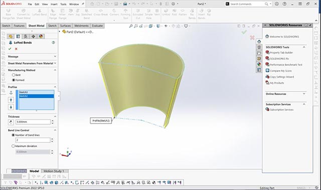
Lofted Bends: Lofted Bends allow for the creation of parts that transition between two profiles along a defined path, making it possible to design parts with curved or irregular shapes. This feature is particularly useful for creating complex ductwork, transitions, and other components that require a smooth flow between different cross-sections. To use Lofted Bends, you must create two or more profiles on separate planes and then use the “Lofted Bends” tool to generate the transition between them.
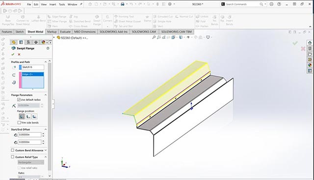
Swept Flanges: Swept Flanges are another powerful feature for creating parts with non-linear bends. This tool allows you to sweep a profile along a path, creating bends that follow the path’s curvature. Swept Flanges are ideal for designing parts with continuous bends or twists, such as spiral ducts or components with ergonomic curves.
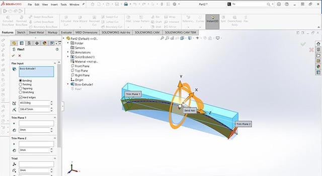
Flex Feature: The Flex feature offers the ability to bend, twist, taper, and stretch solid and surface bodies after they have been modeled. This feature is particularly useful for applying final adjustments to sheet metal parts, allowing for bending or twisting in ways that standard bending tools cannot achieve. By accessing the Flex feature under “Insert → Features → Flex,” designers can manipulate complex geometry to meet specific design requirements.
Tips for Using ‘3D Sketches’ and the ‘Convert to Sheet Metal’ Tool
For parts that cannot be created directly using sheet metal features, SolidWorks allows designers to model the part as a solid body and then convert it into a sheet metal part:
Use 3D Sketches: Start by creating a solid model of the part using 3D sketches to define the complex shapes and paths. This approach is useful for parts with geometries that are difficult to create using standard sheet metal tools.
Convert to Sheet Metal: Once the solid model is complete, use the “Convert to Sheet Metal” tool to convert the model into a sheet metal part. This tool allows you to select a fixed face as the base, specify the material thickness, and define the bends. It’s essential to ensure that the solid model is designed with manufacturability in mind, considering factors such as bend radii and material thickness.
By leveraging the advanced features in SolidWorks, following best practices for designing with irregular bends, or by outsourcing to a sheet metal design company, designers and drafters can easily create complex sheet metal parts.
Customizing Bend Features to Meet Specific Design Requirements
Modifying the default bend parameters in SolidWorks is essential for meeting specific design requirements and ensuring the manufacturability of sheet metal parts. Here are the steps to modify bend parameters such as bend radius and bend allowance:
Modify Bend Parameters: Access the Sheet Metal feature in the FeatureManager design tree. Right-click and select “Edit Feature.” Here, you can manually adjust the bend radius and bend allowance to meet your design requirements.
Create Custom Bend Tables: SolidWorks allows you to create custom bend tables that store bending information for different materials and thicknesses. To create a custom bend table, navigate to the location where SolidWorks reads the bend tables (Options ⟩System Options ⟩File Locations), and use the sample tables provided by SolidWorks as a reference to create your own. Input the calculated values for bend allowance, bend deduction, and K-factor for each material and thickness.
Using Custom Properties and Configurations in SolidWorks for Sheet Metal Bending
Custom properties and configurations in SolidWorks can manage multiple variations of a part with different bend characteristics:
Custom Properties: Use the CustomPropertyManager interface to manage custom properties associated with the model, configurations, or cut-list features. Custom properties can store metadata, such as part number, material type, and specific bend parameters.
Configurations: Create different configurations for a part, each with its own unique set of bend parameters. This allows for easy switching between different design variations without the need to create separate part files.
Tips for Reducing Material Waste through Optimal Bend Sequencing
Planning the sequence of bends is crucial for minimizing material usage and avoiding collisions during bending:
Plan Bend Sequence: Analyze the part geometry to determine the most efficient sequence of bends. This helps reduce the amount of material used and prevents potential collisions or interference during the bending process.
Flatten Feature: Use the Flatten feature in SolidWorks to preview the flat pattern of the part. This allows you to visualize the unfolded geometry and adjust the bend sequence accordingly. The Flatten feature can be found under the Sheet Metal tools in CommandManager.
Nesting Parts: For optimal material utilization, nest parts in the flat pattern layout to reduce scrap material. This involves arranging the parts in such a way that they share common edges or fit within the negative spaces of larger parts.
Bring down material waste and control usage with accurate bend sequence
Macros in SolidWorks can automate repetitive sheet metal design tasks, saving time and increasing productivity:
Introduction to Macros: Macros are scripts that can automate tasks in SolidWorks. They can be recorded, edited, and run to perform a series of commands with a single action.
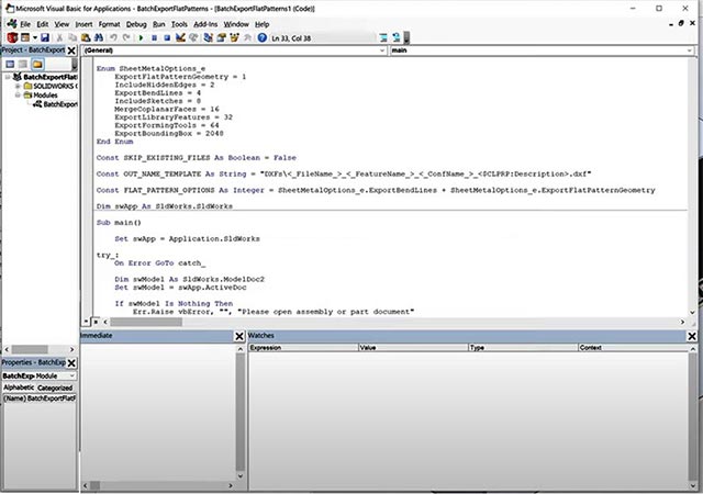
Macro Examples: Examples of macros for sheet metal design include automating the creation of standard features like flanges and holes, or generating SolidWorks flat patterns for multiple parts. These macros can be created using SolidWorks API and VBA programming.
Using Macros: To record a macro, go to Tools ⟩Macro ⟩Record. Perform the tasks you want to automate and then stop the recording. You can edit the macro by going to Tools ⟩Macro ⟩Edit. To run a macro, use Tools ⟩Macro ⟩Run. Macros can significantly streamline the design process by automating repetitive actions.
By customizing bend features, utilizing custom properties and configurations, planning bend sequences, and employing macros, designers can optimize their sheet metal designs for both performance and material efficiency. These features in SolidWorks offers immense efficiency to the designer compared to other CAD tools in seamless design of sheet metal bends.
Considering Design for Manufacturability &Assembly (DFM)/(DFMA)
Design for Manufacturability (DFM) and Design for Manufacturing and Assembly (DFMA) strategies are essential for creating efficient, cost-effective, and manufacturable sheet metal designs, especially when it comes to bending operations. Here are some strategies and best practices for a bending design that align with DFM and DFMA technique for sheet metal design:
DFM Strategies for Bending Design
Material Selection: Choose materials that are readily available and suitable for bending. Consider physical properties like the material’s thickness, tensile strength, and ductility to ensure it can be bent without cracking or excessive springback.
Standardize Bend Radii: Use standard bend radii to minimize the need for special tooling and simplify the bending process. This can lead to cost savings and more predictable manufacturing outcomes.
Bend Relief: Incorporate bend relief into designs to prevent material from tearing during the bending process, especially for acute bends.
Tolerances: Design with manufacturable tolerances in mind. Overly tight tolerances can be unnecessary and expensive, so ensure tolerances are as loose as possible while maintaining functionality.
Avoid Features Near Bends: Keep holes, notches, and other features at a safe distance from bend lines to prevent deformation and to maintain the integrity of the part.
Bend Sequencing: Plan the sequence of bends to minimize tool changes and reorientations of the part, reducing bending time and the potential for errors during fabrication.
Collaboration with Fabricators: Engage with Fabricators early in the design process to leverage their expertise and ensure that the design is optimized for the available tooling and machinery.
DFMA Strategies for Bending Design
Integrate Design and Manufacturing: Consider both the design and manufacturing processes together to optimize the parts for ease of fabrication and assembly.
Minimize Part Count: Reduce the number of unique parts by designing multifunctional components and using common joints and fasteners. This can decrease complexity and assembly time.
Self-Locating Features: Design parts with features like tabs and slots that simplify assembly and reduce the need for additional fasteners.
Uniform Wall Thickness: Maintain uniform wall thickness throughout the design to avoid issues with material flow during fabrication.
Nesting for Material Utilization: Design for efficient nesting to maximize material utilization and reduce waste. This involves arranging the parts in such a way that they share common edges or fit within the negative spaces of larger parts.
Tolerance Analysis: Conduct a thorough tolerance analysis to ensure parts will fit together properly without the need for excessive adjustments during assembly.
Software Tools: Utilize software tools that incorporate DFM and DFMA checks to automatically identify potential manufacturing issues in your designs.
By leveraging these SolidWorks tools, designers can effectively share their designs with fabricators, ensuring that all parties have a clear and consistent understanding of the project. This collaborative approach helps minimize errors, accelerate time to market, and ultimately lead to a more efficient and successful product development process.
Conclusion
The key to successful sheet metal design lies not only in mastering the software but also in understanding the material properties and the impact of design decisions on manufacturability and product functionality. Whether you’re a beginner looking to get started with sheet metal design or an experienced professional seeking to refine your design models, a skilled SolidWorks engineer can help you develop your desired outcome.
Leverage DFM strategy for your sheet metal for fabrication without bending the rules.
Tags: Sheet Metal BendingSheet Metal Parameters in SolidWorksSolidWorks for Sheet Metal Bending
Authored by:
Nimesh Soni with 15+ years of managerial role in industrial design industry, manages furniture design vertical at HitechCADD Services. For the past 9 years at Hitech, he has delivered winning solutions for a range of turnkey projects with his expertise in SAP/PLM and CAD tools. His current research work towards a doctoral degree in IOT gives him an advantage in identifying automation opportunities across design-to-manufacturing cycle.
To provide the best experiences, we use technologies like cookies to store and/or access device information. Consenting to these technologies will allow us to process data such as browsing behavior or unique IDs on this site. Not consenting or withdrawing consent, may adversely affect certain features and functions.
Functional
Always active
The technical storage or access is strictly necessary for the legitimate purpose of enabling the use of a specific service explicitly requested by the subscriber or user, or for the sole purpose of carrying out the transmission of a communication over an electronic communications network.
Preferences
The technical storage or access is necessary for the legitimate purpose of storing preferences that are not requested by the subscriber or user.
Statistics
The technical storage or access that is used exclusively for statistical purposes.The technical storage or access that is used exclusively for anonymous statistical purposes. Without a subpoena, voluntary compliance on the part of your Internet Service Provider, or additional records from a third party, information stored or retrieved for this purpose alone cannot usually be used to identify you.
Marketing
The technical storage or access is required to create user profiles to send advertising, or to track the user on a website or across several websites for similar marketing purposes.
![Sheet Metal Bending in SolidWorks:The Ultimate Guide [2024]](https://www.hitechcaddservices.com/wp-content/uploads/2024/07/sheet-metal-designs-in-solidworks.jpg)