HVAC drawings and blueprints are essential for construction projects, to ensure alignment with design and compliance with codes, facilitate precise installations, reduce errors, and ease future maintenance. Digitalization, BIM, IoT, and AI-driven predictive maintenance enable sustainable and eco-friendly HVAC alternatives.
Table of Contents
HVAC drawings are indispensable deliverables for new construction and renovation projects. For new constructions, these drawings ensure that the HVAC systems align with the project design and performance needs.
For renovation projects, HVAC blueprints facilitate efficient modifications and expansion of existing systems by complying with building codes and regulations.
This guide provides a comprehensive understanding of HVAC drawings and their role in the HVAC industry.
Constructing or renovating a building to ensure required occupant comfort and indoor air quality requires high performance Heating, Ventilation, Air Conditioning (HVAC) systems.
Accurate and detailed HVAC design drawings ensures that all building systems work seamlessly and efficiently. These drawings serve as a technical blueprint, providing a visual roadmap for precise HVAC system installation, reducing design errors, and enabling efficient HVAC maintenance. They also help with HVAC troubleshooting, ensuring compliance with HVAC code requirements and ASHRAE standards while enhancing energy efficiency and airflow management.
Without precise and updated HVAC drawings, the entire process from design to maintenance would lead to challenges, including energy inefficiencies, increased costs, design errors, compliance issues, and misalignment with building layout.
Well-drafted HVAC detail drawings ensure precise equipment placement, optimize airflow management, and streamline ductwork design to achieve energy-efficient, code-compliant, and comfortable indoor environments.
HVAC blueprints and drawings serve as a visual representation of HVAC systems, providing detailed insights into HVAC layout, ductwork design, and equipment placement. These drawings go beyond mere aesthetics and serve as a principal lifeline for any project. They communicate intricate details for the design, layout, and functionality for technicians, contractors, and building maintenance professionals.
HVAC systems play a significant role in buildings to achieve the required air quality, temperature control, and comfort. Understanding the basics of Heating, Ventilation, and Air Conditioning is critical for HVAC contractors, owners, and building managers to achieve a habitable indoor environment.
HVAC systems include heating components, including boilers, heat pumps and electric heaters. They also include distribution systems such as pipes or ductwork for water or air distribution. Ventilation systems include indoor and outdoor air exchangers, air filters, and exhaust fans to remove pollutants, moisture, odor, pollen, and stale air from buildings.
Air conditioning systems consist of a thermostat, cooling sources, and humidity control to remove heat from indoor air, maintain a comfortable air temperature, and maintain humidity levels.
To understand HVAC system design and interpret HVAC drawings, familiarity with HVAC components and configurations is essential. The following diagram illustrates the basic components of an HVAC configuration in a building:
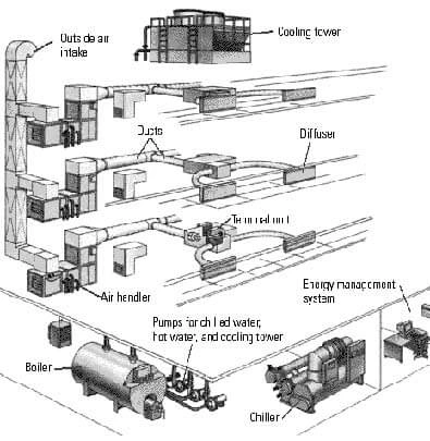 Source: Research Gate
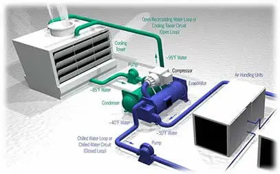 Source: Instrumentation Tools
Heating, Ventilation, and Air Conditioning (HVAC) systems play a crucial role in improving occupant comfort within a building. These systems regulate air quality, temperature, and humidity and achieve efficient ventilation to circulate fresh air, remove pollutants, and promote healthier living. Maintaining optimum humidity levels prevents excess moisture or dryness, which can lead to health problems and discomfort. Overall, HVAC components are essential to creating a productive, healthy, and comfortable ecosystem to enhance the quality of life for occupants within a building.
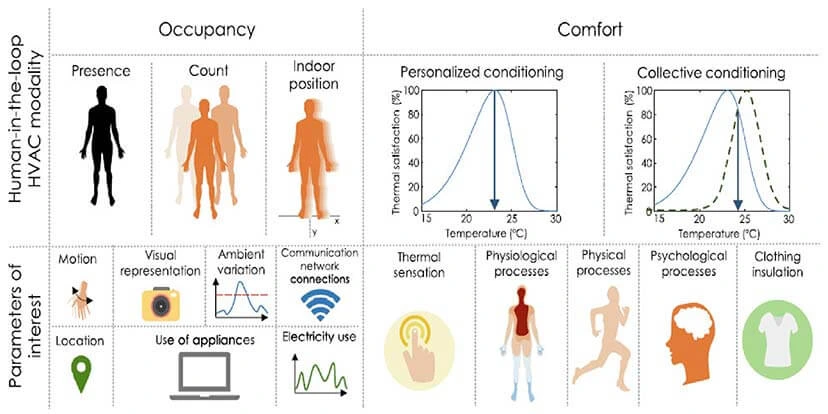 Source: mdpi
HVAC drawings, including schematic drawings, plan drawings, elevation drawings, isometric drawings, and shop drawings, serve as essential technical documents that represent the HVAC design, layout, and installation of HVAC systems
HVAC shop drawings are especially created for installation and fabrication of MEP components. Each drawing serves a unique purpose of delivering valuable information to architects, contractors, engineers, and other stakeholders. Every HVAC drawing serves a specific purpose. This section focuses on various HVAC drawings that are explained in detail with their intended use.
 HVAC Schematic Drawing
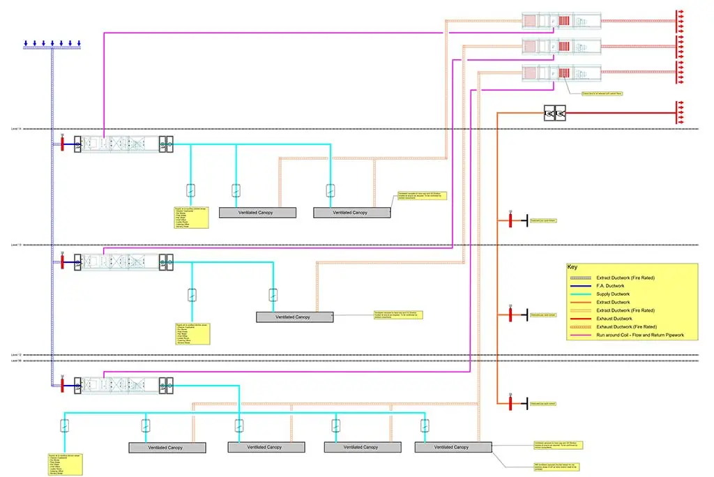
Schematic drawings deliver a simple representation of an HVAC system to emphasize air flow and energy. These drawings provide an effective overview of system design and are used for planning purposes. HVAC Schematic drawings highlight the functional aspects of components and systems rather than dimensions or details. They encompass HVAC components and their interconnections, including fans, air handlers, coils, sensors, valves, and sensors. Schematic drawings are essential for architects, HVAC engineers, and other professionals to understand the flow and logic of an HVAC system.
 HVAC Layout Plan
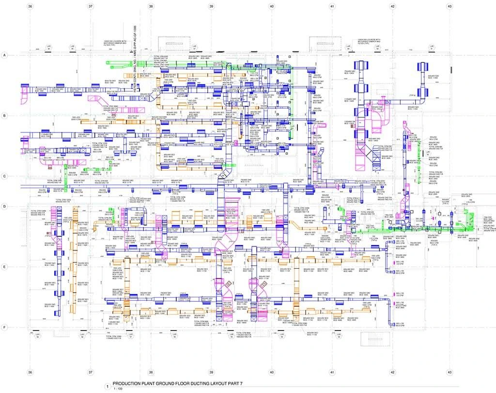
Plan drawings in an HVAC configuration depict a 2D illustration of the HVAC system from a top view. These drawings provide a clear view of HVAC components and their placement within a space or building. HVAC plan drawings are drawn to scale to locate ductwork, equipment, registers, vents and other HVAC elements to help understand the spatial arrangement of HVAC systems within a structure and their relationship with architectural systems.
Elevations drawings within the sets of HVAC drawings reveal the system’s various views, including front, side, and rear, and provide in-depth information about the location, height, and orientation of HVAC elements with reference to structural components. HVAC elevation drawings ensure that HVAC components do not clash with other building systems. Specific sections of the HVAC system, such as ducts or wall-mounted equipment, are represented in a vertical format within elevation drawings.
 Spool Isomatric Drawing
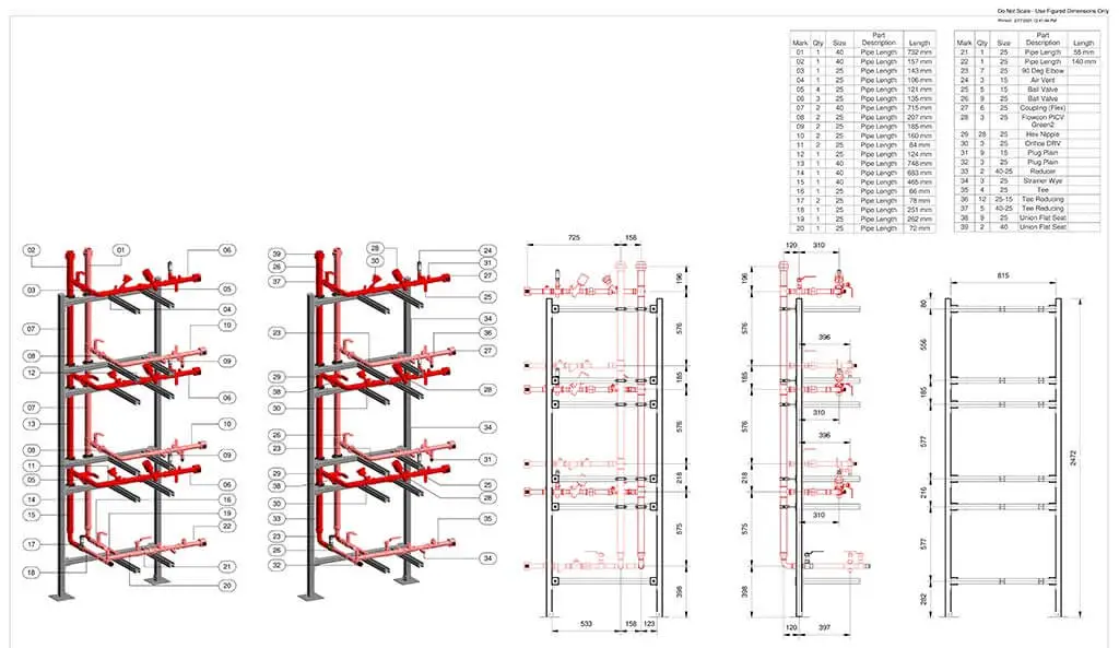
Isometric drawings represent the HVAC configuration in a 3D format to provide higher realism and the arrangements of components in space. HVAC elements in 3D are projected on a 2D plane at a 30-degree angle to envision spatial relationships and the layout more accurately. HVAC isometric drawings are useful for planning HVAC systems that contain multiple interconnected components and leverage a 3D perspective for greater clarity.
One must develop the skills to understand and interpret HVAC drawings effectively. While it is important for architects and designers to understand HVAC drawings for design intent, contractors must understand HVAC shop drawings used for fabrication and installation of HVAC components. This section covers the essential knowledge required to read HVAC blueprints.
HVAC engineers require a good grasp of scale and measurements to read HVAC blueprints. Scale is a key to HVAC drawings because it allows for an accurate representation of dimensions. It is represented as
– 1/4” = 1’, indicating the blueprint’s focus on measurements and scale.
HVAC drawings utilize legends and symbols to illustrate various components and systems. This section covers common legends and symbols utilized in HVAC drawings.
The ability to accurately identify HVAC symbols and legends used in HVAC drawings supports architects and engineers to visualize elements like vents, fans, ducts, and thermostats.
Color-coding of legends is critical in HVAC blueprints, as diverse colors depict multiple systems. Identifying and differentiating these colors provides a better understanding of system functionality.
Arrows and directional symbols are used to represent air flow and fluid movement within the HVAC system diagram. Interpreting arrows precisely is important to ensure optimum air circulation and system functionality.
Familiarity with specifications and material codes found within legends is vital to selecting the right set of materials. Codes include details of pipe material, insulation type, and HVAC equipment specifications, which impact HVAC performance.
Dimensions and notations provide key information on the location, size, and specifications of HVAC elements. Dimensions and annotations are represented by arrows, symbols, and numbers that help designers and installers to collaborate.
Accurate comprehension of annotations and dimensions ensures systems are installed to specifications for optimal performance and energy efficiency.
Reading abbreviations within HVAC drawings is essential to understanding HVAC system plans. Abbreviations like Cubic Feet per Minute (CFM) for airflow measurement, British Thermal Unit (BTU) for heat energy, etc., are universal abbreviations for HVAC professionals. Other abbreviations include Variable Air Volume (VAV), Air Handling Units (AHU), Ducts (D), and Roof Top Units (RTU). Ensuring the efficient installation and maintenance of systems backed by enhanced communication within stakeholders requires a clear understanding of HVAC blueprints.
Generating HVAC drawings requires the use of specialized HVAC design software and drafting tools. Industry-standard applications like Revit, CAD help designers create detailed HVAC blueprints with precision. These tools assist in illustrating the HVAC equipment layout, ductwork design, air handling units (AHUs), ventilation systems, and precise piping layouts.
 HVAC Piping Plan
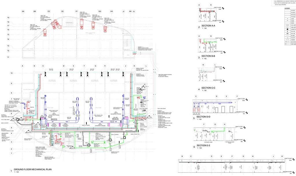
Additionally, it facilitates collaboration and communication between architects, engineers, and contractors for the seamless integration of systems within building design. Accurate HVAC shop drawings extracted from 3D Revit models enable contractors and manufacturers to gain seamless installation and fabrication of MEP elements. HVAC software solutions also help professionals optimize HVAC system performance, improve energy efficiency, and ensure compliance with ASHRAE, SMACNA, and local building codes. These tools aid in minimizing clashes in MEP coordination, reducing energy consumption, and achieving thermal comfort and indoor air quality (IAQ) standards.
Gather Project Information
Draw Layouts and Schematics
Label and Annotate
Review and Quality Control
Documentation and Delivery
Require 3D modeling for seamless HVAC installations?
Contact us now »HVAC drawings need to adhere to regulations and building codes for efficiency and safety. This section will explain the significance of compliance and how it can be attained.
System schematics: Produce in-depth schematics to outline the HVAC system and include details for ductwork routing, equipment placement, and control systems to ensure a clear representation of the system design.
Load calculations and efficiency: HVAC drawings need to incorporate load calculations to accurately determine heating and cooling needs. Compliance with codes requires energy efficiency standards that can be achieved with calculations to ensure optimum and efficient operation of the system while complying with code requirements.
Adherence to code: Compliance with building codes and regulations is critical in HVAC design, as designers and engineers must have a core understanding of local, state, and national codes to ensure components, materials, and installation meet environmental and safety requirements.
Safety measures: HVAC drawings incorporate safety features that include fire suppression systems, gas leak detection, and ventilation control. These measures not only help protect building occupants, but also adhere to safety regulations and codes for HVAC systems.
Accessibility and maintenance: Considering accessibility and maintenance repairs, accurate HVAC drawings in compliance with building codes for accessible service points, clear labels, and accurate documentation for reliability and safety.
Accuracy and efficiency are crucial to creating HVAC blueprints. This section will provide best practices for designing and drafting quality drawings.
Building Analysis: Perform a thorough analysis of a building layout, orientation, and occupancy patterns with parameters including windows, insulation, and ventilation needs to design and size the HVAC system.
Integrate Energy Efficiency: Incorporate modern HVAC technologies like speed motors, programmable thermostats, and zoning to optimize the system for maximum efficiency and reduce operational costs.
Load Calculations: Conduct precise heating and cooling load calculations using industry-standard methods like Manual J, Manual D, and ASHRAE guidelines. Proper load sizing prevents overcooling, overheating, high energy bills, and system inefficiencies. Oversized and undersized HVAC systems lead to occupant discomfort and increased HVAC maintenance costs.
Ductwork and Air Distribution: Meticulous attention to air distribution and ductwork design ensures balanced airflow throughout the entire building. Appropriate duct sizing and zoning must be carried out to match cooling and heating requirements in different sections.
Compliance with Codes and Regulations: Stay updated with energy efficiency, building codes, and safety regulations while drafting HVAC drawings. Drafting HVAC drawings needs to comply with industry standards to avoid expensive revisions, ensure safety, and build occupant comfort.
To ensure efficient system installation, the accuracy and clarity of HVAC blueprint creation is important. Precise measurements, complete schematics, and clear labels support contractors in interpreting plans correctly to reduce errors and rework.
Collaboration with other trades, such as electrical, plumbing and fire protection systems is often necessary for construction projects. Close coordination with architects, electricians, and plumbers ensures accurate placement of HVAC systems, ductwork routing, and energy-efficient designs. This minimizes conflicts and improves project efficiency, which results in environmentally friendly and cost-effective HVAC results.
Now that we have understood the basics of creating HVAC drawings, we will focus on reverse engineering – analyzing and reading existing HVAC blueprints.
We will examine a typical HVAC blueprint and ways to navigate through multiple sections and components.
Identifying HVAC Components: The first step is identifying core components that include air-handling equipment, ductwork, and thermostats. This helps technicians understand the HVAC system layout and functionality.
Analyzing Ductwork Layouts: Analyzing ductwork sizing and pathways is critical. Technicians evaluate airflow calculations, duct sizes, and their distribution to ensure optimum air circulation throughout the building.
HVAC Equipment Placement: The analysis of a blueprint illustrates the strategic placement of HVAC elements. Accurate positioning of evaporators, condensers, and air handlers is key for effective performance and maintenance ease.
Electrical Connections: Electrical diagrams within the HVAC drawing outline control and wiring systems. HVAC engineers need to check these details to ensure precise connections, proper voltage, and safety measures.
Load Calculations and HVAC Zoning: To determine system cooling and heating needs accurately, load calculations need to be performed based on drawing data and considering parameters like building size, insulation type, and building occupancy to ensure an HVAC system meets project needs efficiently.
In this section, we will learn how to identify and explain the various HVAC elements and configurations depicted in blueprints.
Interpreting HVAC Blueprints: Read and comprehend HVAC drawings that include floor plans, mechanical drawings, and elevations to recognize the design and layout of HVAC systems.
HVAC System Components: Identify important HVAC components within drawings like condenser units, air handlers, thermostats, ductwork, air terminal, insulation and dampers to gain an understanding of system functionality.
Understanding HVAC Systems: Check blueprints to determine the type of HVAC system used, including hydronic heating, combined systems, or hydronic heating for maintenance and troubleshooting.
Zoning and Distribution: Identify ductwork layout and zoning configurations within blueprint to identify the movement of conditioned air through a building to ensure efficient cooling and heating.
Code Compliance: Verify HVAC elements in drawings comply with local building codes and regulations to ensure safe installations and renovations.
Blueprints play a significant role in the installation process, as they serve as a visual roadmap and deliver an in-depth guide for builders and technicians. These blueprints indicate precise measurements, placement and materials to ensure accuracy and uniformity within construction.
These documents set support coordination among various HVAC engineers, mechanical contractors, and MEP professionals, reducing errors and expediting HVAC system installation process. HVAC blueprint accuracy facilitates efficient communication between various teams and stakeholders to allow for adjustments and modifications. HVAC blueprints ensure that projects meet design specifications and standards.
HVAC blueprints play a significant role in ensuring that HVAC systems align with planned design specifications. These accurate and detailed technical sheets serve as a guide for HVAC engineers and professionals for installation and maintenance tasks. By using detailed ductwork layouts, mechanical piping plans, and ventilation drawings, engineers can ensure that elements such as ductworks, piping routes, and equipment placement conform to planned designs while optimizing energy efficiency and airflow distribution.
As buildings evolve over time, HVAC blueprints become crucial for renovations and upgrades to ensure modifications align with the planned design intent. Furthermore, blueprints are a vital tool for maintaining optimum energy and comfort within a structure.
HVAC drawings play a key role in mitigating installation errors to save time and resources by lowering revision needs. They deliver an in-depth overview of HVAC systems to deliver accurate instructions to technicians and contractors.
By visualizing the layout, equipment placement, and ductwork, the blueprints help teams analyze potential problems and resolve them before actual construction starts. This preemptive approach enhances efficiency and reduces reworks and overruns. Reducing errors with HVAC drawings ensures seamless installation and optimal performance of climate control within building projects.
Because HVAC systems need perpetual maintenance and troubleshooting, we will illustrate how HVAC drawings are significant for these processes.
HVAC sheets are effective tools for system maintenance, as they are intricate diagrams that serve as a visual guide for the HVAC infrastructure. Maintenance teams need to rely on these drawings to assess crucial components, such as piping, ductwork, and component locations, to ensure system inspection.
With a complete understanding of the hvac duct layout drawing, technicians can create HVAC maintenance strategies, build maintenance procedures, schedule maintenance runs and troubleshoot problems faster. Furthermore, these drawings aid in identifying system efficiency and making informed modifications, streamline maintenance efforts, improve system longevity, and ensure indoor air quality and comfort for building occupants.
Identifying and resolving HVAC component problems becomes effective and efficient by referencing original HVAC drawings. These detailed schematics deliver invaluable insights into system layout and design to enable engineers to pinpoint problems quickly. If there is inadequate airflow, HVAC blueprints reveal ductwork configuration to aid in the identification of blockages and obstructions. Furthermore, when dealing with problematic temperature control, HVAC blueprint diagnostics locate sensor placements and thermostats to streamline replacements or adjustments.
Cross-referencing master plans, HVAC engineers can ensure effective and efficient repairs to enhance system performance, energy efficiency and indoor comfort. This leads to mitigating costs and downtime to diagnose and resolve issues.
Over time, HVAC systems may undergo modifications or upgrades. To ensure efficient and compliant heating, HVAC blueprints need to be updated and revised. This is done through thorough reviews of existing blueprints and identifying required modifications that include adding new equipment, assessing modifications, modifying ductwork and optimizing air flow patterns.
Collaborating closely with architects, engineers, and contractors to incorporate design changes accelerates the update and revision process for blueprints. Using CAD-based software to create alterations, make precise measurements, and produce clear annotations along with energy-efficient HVAC solutions and conformance with building codes enriches the update and revision process.
Conducting simulations and quality checks validates revised blueprints to ensure that HVAC systems meet performance and sustainability goals while avoiding cost overruns.
Digitalization is revolutionizing the AEC industry, with BIM serving as the cornerstone of HVAC design. BIM has helped stakeholders create detailed 3D representations of HVAC elements to facilitate accurate planning and reduce errors during the construction process.
Intelligent HVAC configurations are evolving through IoT sensors and machine learning (ML) algorithms. These technologies improve indoor comfort and energy efficiency. Predictive maintenance driven by AI ensures preemptive service that mitigates downtime and extends equipment lifespan. As sustainability becomes important, these innovations will play a critical role in producing energy-efficient and eco-friendly HVAC alternatives to meet the demands of fast-paced construction.
As energy costs and environmental concerns continue to grow, HVAC systems and blueprints need to meet strong standards. Green designs and energy-efficient elements are incorporated into HVAC blueprints to lower carbon footprints and reduce operational costs.
New innovations include new-age heat recovery systems, solar-powered HVAC systems, and geothermal heat pumps. ML Algorithms and Smart controls improve energy use by altering HVAC operations in real time, taking into consideration occupancy, energy demands, and weather conditions. Eco-friendly materials to build HVAC components and sustainable refrigerants have gained significance to align HVAC systems toward a green initiative reinforced by sustainable building.
HVAC drawings serve as a bridge between conceptual design and practical application to ensure that HVAC components function at optimal levels based on regulatory standards and comfort. Whether you are a designer, contractor, technician, or maintenance professional, a solid grasp of HVAC blueprints along with accurate HVAC shop drawings is a need to achieve success in the HVAC sector.
Architects, designers, and engineers can make informed decisions, as these HVAC blueprints provide visualization for an intricate duct network, pipes, and other equipment for improved comfort. As technology evolves, and environmental concerns become prominent, these drawing become crucial in creating sustainable and eco-friendly systems, reducing energy consumption and minimizing their carbon footprints.
HVAC drawings are technical diagrams that illustrate the layout of heating, ventilation, and air conditioning systems. They include ductwork, piping, equipment locations, and control systems to guide installation and maintenance.
They provide a precise roadmap for installing HVAC systems, reducing errors, saving costs, and ensuring compliance with safety and energy efficiency standards. Blueprints also help coordinate HVAC with other trades like electrical and plumbing.
Blueprints are finalized, detailed versions of HVAC drawings used for actual construction and installation. Drawings, on the other hand, include preliminary designs, schematics, and conceptual layouts before final approval.
They typically contain floor plans, duct layouts, piping diagrams, schedules, legends, and symbols. These details help contractors and technicians understand system components and connections.
Start by reviewing the title block, scale, and legend to understand symbols and abbreviations. Then analyze the layout, equipment placements, and notes for installation details.
HVAC plans use standardized symbols to represent ducts, diffusers, fans, thermostats, valves, and dampers. The legend provides explanations for these symbols to ensure accurate interpretation.
Bhavesh Umraniya is a BIM MEP expert with over 10 years of experience in the mechanical BIM field. Having, worked on multiple MEP projects worldwide, he is always looking for ways to enhance design quality and project productivity through technology interventions and process excellence. His exposure to various residential and commercial sectors, including hotels, airports etc. makes him a go-to authority in the BIM MEP space.
Harika Singh is an academician and published writer. Her passion for engineering and technology reflects in the in-depth coverage she provides on technology trends. 20 years of work association with institutes of repute across India and the US positions her to provide valuable insights to business stakeholders on achieving scalability and operational efficiencies through digitalization.
You may also like
Point Cloud to Revit: The Backbone of Scan to BIM Projects
The Role of Millwork Detailing in Modern Architecture