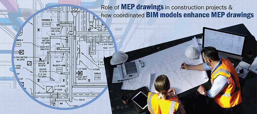
Accurate and clash-free MEP drawings across disciplines ensure 100% installation of building components with minimal change orders. Detailed MEP drawings save construction projects from running into time and cost overruns.
Coordinating BIM MEP (Mechanical, Electrical and Plumbing) systems is an extremely complex process due to the spatial, design and interrelation issues involved between the various MEP systems. The absence of MEP detailing and drawings leads to contractors struggling to resolve spatial issues leading to rework, material wastage and construction errors, ultimately resulting in time and cost overruns.
Making sure a project is structurally sound and MEP clashes are identified and resolved at the pre-construction stage is the true purpose of MEP drawings. With clear and concise MEP drawings, contractors gain a clear roadmap on how to complete the construction process seamlessly within budget and on time. The application of these drawings can be extended to electrical or equipment manufacturing of MEP systems for construction installation to ensure precise, efficient and clash-free component installation.
In this blog, we discuss the challenges, benefits and other aspects related to MEP drawings for BIM.
Table of Contents:
CAD-based MEP drawings come with their own set of challenges that include:
BIM helps contractors, design and engineer the MEP and building layout, wherein project visualization helps foster collaboration between architectural and structural teams.
Save on project cost and time overruns with clash-free MEP drawings
Contact our MEP specialists »MEP coordination harmonizes various building services with other trades to form a strong foundation for onsite construction. Once the MEP coordinated drawings are prepared by the BIM MEP consultant, it is the MEP contractor’s responsibility to carry out detailing, fabrication, and installation.
MEP drawings in building construction enable better fabrication, installation, and schedule as they are coordinated between mechanical, electrical, and plumbing teams.
Fabrication-ready MEP drawings help contractors create precise HVAC, electrical, and plumbing systems based on a complete drawing set. These drawings act as a quick reference source for contractors to assess the conditions of a building system and resolve onsite ambiguities. Contractors and engineers gain seamless onsite installation.
With scaled outlines of installation systems based on precise dimensions, connections, and accessories, contractors and engineers can carry out seamless installation. Contractors and engineers have a clear picture of what needs to be built, fabricated, and installed. With precise locations marked in MEP drawings, contractors can save on time through consistent and reliable onsite installation.
Hitech CADD Services created a 3D MEP BIM Model for a commercial building in the US, as per international standards. The coordinated MEP components generated better insights and saved significant time by eliminating clashes at initial stages of design.
Read Complete Case Study »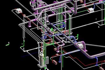
Coordinated MEP drawings improve uniformity and building performance by enabling standardization of MEP systems. Uniform building guidelines allow project stakeholders to stay on the same page while helping contractors easily obtain construction permits and licenses.
With MEP coordination drawings in place, contractors can conveniently get component and material costs. This helps streamline supply chain, reduce material wastage, lowering construction costs and improving planning activity.
While traditional MEP drawings begin in the later stages, BIM-led MEP coordination begins in the early stages of the project lifecycle. BIM has proved to be a crucial differentiator in the creation and application of MEP drawings. A BIM-based approach makes drawing and detailing far more precise, detailed, and reliable.
Information accuracy of BIM-based MEP drawings is highly precise. A well-coordinated BIM model packs in every piece of information at various LOD levels.
MEP BIM models are developed at various LOD levels such as:
Hitech CADD Services created a coordinated 3D MEP BIM model with LOD 300 for a hospital building in Australia. The clash free plumbing layout and hydronic equipment for architectural and structural disciplines resulted in seamless installation detailed drainage systems for underground as well as upper floor drainage systems.
Read Complete Case Study »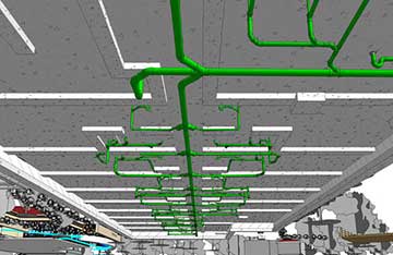 3D MEP BIM model at LOD 300
With each increasing Level of Development, the depth of information becomes detailed and far more precise. Various prefab components and assemblies can be prefabricated based on detailed MEP fabrication drawings. These include sprinkler systems, vertical risers, plant modules for compressors, etc.
3D BIM models are integrated by collaborating disciplines such as architecture, structure, and MEP. Once coordinated and clash-free, these models provide precise and trusted documentation. Contractors can pull these drawings from BIM authoring software like Revit® in various formats such as DWG, PDF, etc. An interference-free MEP drawing makes the onsite installation of various Mechanical, electrical, plumbing and fire protection systems quick and seamless.
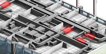
Hitech CADD services created a clash free 3D model in Revit at LOD 400 and MEP coordination drawings for an airport project in Muscat. Clashes were identified and resolved using Navisworks®. A collaborative approach helped the client save $7 million in 6 months, and 100% of MEP systems were installed with minimal change orders based on reduced field conflicts.
 BIM Clash Detection
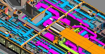 Clash Resolution
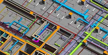 Conflicts Checking
Based on a coordinated and information-rich BIM model, detailed schedules and material takeoffs can be generated for offsite fabrication and onsite installation. BIM MEP shop drawings can be leveraged by fabricators to build equipment, whilst precise schedules reduce material wastage and mitigate construction delays.
RFI’s generally arise when teams require additional information or clarification, or when problems are identified, or a modification is needed. Contractors or sub-contractors submit RFI’s to designers or engineers for drawing clarification, or if there may be concerns about specific building materials, component substitution, etc.
The time to create and receive RFI feedback can be time-consuming causing some parts of construction to be delayed. Every ambiguity is cleared early on in the design stage due to the increase in coordination, resulting in fewer RFI’s being raised. This reduces construction costs, boosts project efficiency and increases turnaround time.
With every contractor or subcontractor looking at a single source of truth, proactive decisions can be taken to make onsite MEP installation quick and hassle-free. A well-coordinated MEP drawing can save in the thousands, and spin-up projects faster. An informed team can draw better scalability, flexibility, quick turnarounds, and lower overhead costs.
Hitech CADD Services created a coordinated 3D MEP BIM model for an institute in Europe with error-free GA drawings and spatial arrangement of the entire plant room- including equipment, connections and arrangement.
The 3D MEP BIM models helped the client easily detect and resolve clashes, make smarter and informed decisions, while saving construction cost with first time right deliverables.
Read Complete Case Study »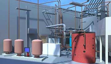 3D MEP Modeling Revit
Streamline onsite activities with 100% accurate MEP design and fabrication.
Contact our MEP experts NOW »MEP drawings are classified into 5 general categories such as penetration drawings, shop drawings, spool drawings, coordination drawings and as-built drawings.
Penetration drawingsMEP systems penetrate floor and wall spaces in the building. Penetration drawings assist contractors and onsite personnel to ensure penetration precision based on precise dimensions. Penetration drawings also assess the structural integrity of buildings and structures to check for future problems.
Shop drawingsShop drawings are crucial for MEP systems and equipment where dimensional accuracy is a necessity. MEP drawings need to account for finer details, manufacturing dimensions, and specific instructions.
Coordination drawingsCoordinating MEP systems help identify and resolve MEP collisions. Coordination drawings enable identification and resolution of clashes to minimize mistakes, cut-down on manufacturing costs and mitigate time overruns.
As-Built drawingsAs-Built MEP drawings help update MEP systems, promote smooth renovation, and enable precise documentation. As-Built documentation also accounts for modifications done in the initial MEP plans.
Spool DrawingsPipe spool drawings are required to manufacture customized and dimensionally precise spools for smooth plumbing installation.
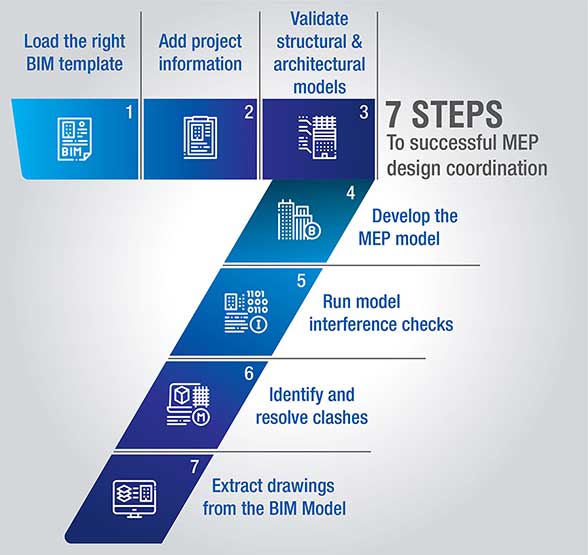
BIM will continue to become robust with automation tools. Automating MEP designs using Dynamo, APIs, and other plugins will ensure success in onsite construction.
BIM is rapidly being adopted in the AEC industry based on coordination, productivity, and performance analysis. For many firms, this indicates a rapid transition from traditional 2D CAD to 3D modeling to achieve a generative design. Project teams need to identify efficient workflows to build precise and detailed MEP drawings, as per client requirement.
BIM adoption for projects in the early stages can enable MEP drawings to be more productive and effective for onsite construction. Firms can leverage the power of Revit MEP to create and derive value from 3D models, whilst Navisworks would act as a glue for design coordination and reviews.
Get accurate schedules & material takeoff’s with 3D BIM MEP shop drawings.
Connect with our MEP team today »You may also like
BIM-Based MEP Coordination for Multi-Trade Collaboration
How AI and ML are Shaping the Future of Scan to BIM
Cabinet Shop Drawings: A Detailed Guide