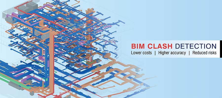
BIM clash detection and resolution enabled by interdisciplinary BIM coordination reduces costly rework, project delays and budget overruns. The clash detection process in the pre-construction stage is supported by Revit® and Navisworks®.
Coordinated BIM models ensure perfect synchronization between architectural, structural and MEPF disciplines. So, whether you are a building engineering consultant, architectural firm or a contractor, if you have leveraged the power of BIM coordination, you can be sure of zero unwanted surprises springing up during construction stage. All conflicts and clashes are addressed by systematic BIM clash detection and resolution using Revit and Navisworks, right at the pre-construction stage.
In this article, we talk at length about what is clash detection, the need for clash detection, the types and benefits of clash detection etc.
Table of Contents
Clash detection refers to identifying and resolving conflicts between different trades in a building construction project.
The process involves the following steps:
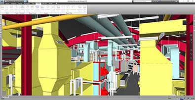 3D Revit MEP coordinated model for plant room
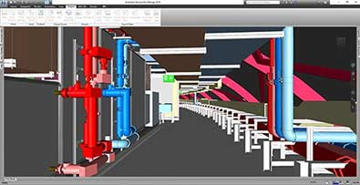 3D MEP model for plant room

Don’t have the time to read the entire article right now?
That’s Ok. Let us send you a copy so you can read it whenever you want to. Tell us where to send it.
Clashes occur when architectural, structural, and MEPF models are integrated into a single federated 3D model, revealing conflicts between the individual models. The process begins with the creation of a 3D BIM model using Revit from drawings, images, or other PDF files, starting with the architectural set. Structural engineers then create their 3D model, aligning it with the architectural layout.
HVAC engineers, plumbing designers, electrical engineers, and fire protection specialists each develop their own 3D models to integrate with the architectural and structural layouts. Each discipline’s 3D BIM model contains its own dataset, including documents, project files, geometric data, and other vital information about the built asset.
The challenge is to combine these individual 3D models into a single, coordinated 3D model to detect clashes. Simply put, clashes are identified in a 3D model when the spatial coordination of the individual models reveals overlaps and conflicts.
There are several reasons why clashes may occur in BIM models. Some of the common causes include:
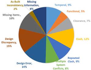 Percentage of design issues analysed across two case studies
To prevent clashes, AEC stakeholders can implement several strategies, such as:
Traditional 2D CAD drawings lack the accuracy, data integrity, and visualization needed for efficient fabrication and installation. These error-prone 2D drawings often require extensive manual intervention, leading to data silos, fragmentation, data loss, and outdated file sets. As a result, projects face rework, cost overruns, and delays.
Some of the challenges stakeholders encounter when using legacy tools for clash detection include:
BIM clash detection is typically conducted during the pre-construction or design phase for various disciplines, using tools like Revit and other visualization software such as Navisworks. Identifying and resolving clashes early in the design process minimizes rework, facilitates smoother planning, and ensures seamless construction. Accurate Bills of Quantities (BOQs) and Bills of Materials (BOMs) contribute to error-free installation and fabrication, ultimately saving both time and costs.
Using Navisworks for clash detection enhances collaboration across multiple trades and ensures more efficient and effective project outcomes.
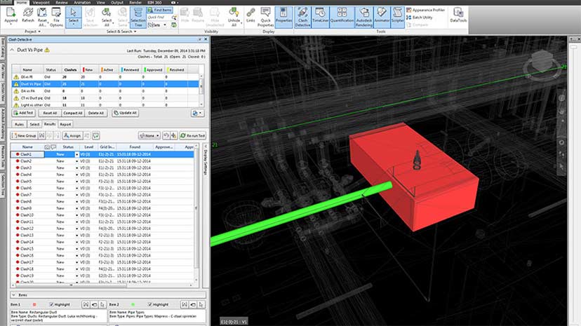 Clash Detection of Duct Pipe
BIM-based tools and technology offer a host of advantages to AEC stakeholders. Adopting BIM can help architects, engineers and consultants to save up to 70% of construction rework caused by design and engineering errors. Here are some major benefits of BIM clash detection:
Coordinated fabrication, construction, and installation drawings, extracted from clash-free 3D models, offer high geometric accuracy and precise installation of all building elements. Accurate fabrication ensures that components are manufactured correctly, reducing manufacturing waste and speeding up onsite installation. Improved drawing accuracy results in less rework, fewer project delays, and timely project completion.
Eliminating member interferences or clashes in the coordinated 3D model reduces design iterations, as the model and drawings are finalized without any confusion. Fewer iterations save project time, reduce costs, and minimize rework during construction.
Integrating 3D models from various disciplines, such as Architecture, Structure, and MEPF, enhances both interdisciplinary coordination and collaboration among construction stakeholders. By accessing a coordinated 3D model on a Common Data Environment (CDE) or allowing project participants to use the model in real time on platforms like BIM360, inter-trade communication is improved. This results in the complete elimination of clashes during the pre-construction stage.
Interference-free 3D BIM models enhance both accuracy and efficiency. By eliminating all clashes in the early stages, fabrication efficiency improves, and the precision of building component installation increases. This process removes hard clashes, tolerance issues, and workflow problems. A 4D BIM model, which adds the dimension of time, can simulate the complete sequence of events for equipment, materials, activities, and other logistical aspects. This is achieved through detailed schedule visualization within the Navisworks timeliner.
An estimated 30% of work done during construction can be attributed to rework.
Extracting BOQs and BOMs from a clash-free 3D BIM model enhances the accuracy of material calculations for manufacturing and installation budgets. This helps reduce material quantities and lower material costs. Additionally, it improves material logistics, optimizing site usage.
Onsite risks can pose a significant threat to field personnel due to the lack of clear visualization provided by 2D plans. Using outdated or incomplete 2D CAD deliverables, without proper compliance and standards, can lead to site hazards. Attempting to access hard-to-reach areas without adequate visualization increases the risk of accidents, resulting in project delays and higher costs.
A clash-free 3D model with 360-degree visualization offers complete clarity for the building project. Field personnel can use AR/VR technology to walk through the model, gaining insights into the position, geometry, description, and other necessary information to operate efficiently.
There are several types of clashes that can occur in architectural, structural, and MEP layouts and designs. BIM helps identify and resolve these clashes, leading to error-free construction. The main types of BIM clashes are:
The clash detection process begins by using the master 3D model in Navisworks or similar software. Below is a flowchart that outlines the entire clash detection process within a BIM framework, making it easier to understand.
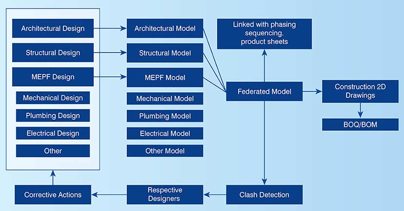
Even a compliant building design may have issues that lead to inefficiencies. Architects, engineers and contractors use BIM clash detection procedures to generate clash reports, identify potential conflicts, and resolve them before the design review and final approval.
STEP 1: A clash report is generated by using two 3D models from different trades within Navisworks.
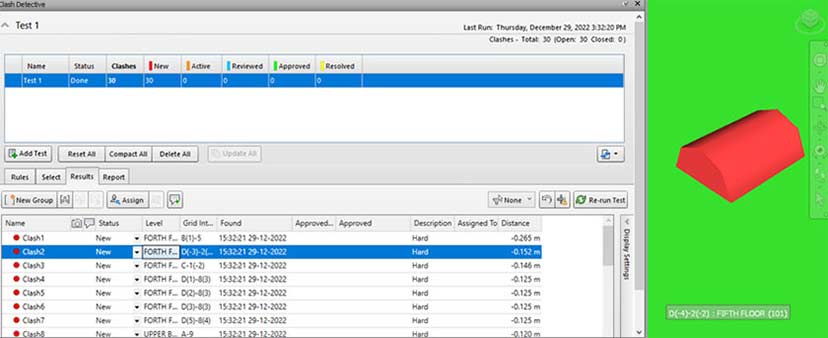 Clash report with highlighting the element
STEP 2: An additional 3D model is uploaded into Navisworks for coordination with the first trade model.
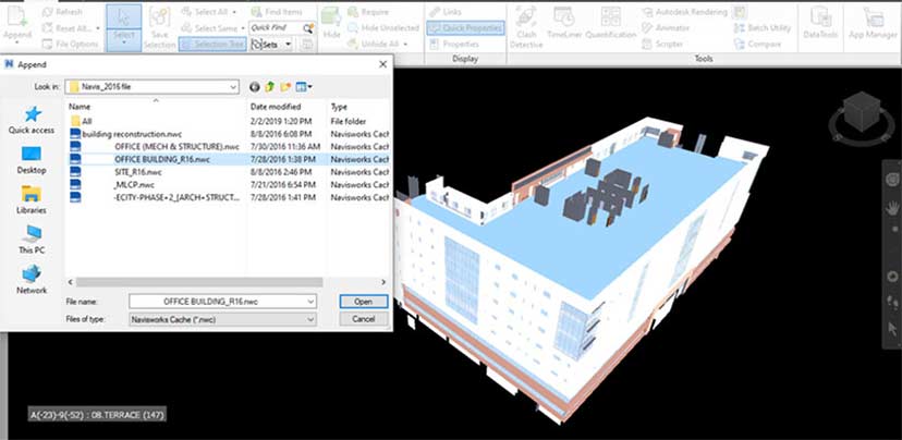 Adding another discipline model to run the clash
STEP 3: The clash detection process begins by selecting the two models. A suitable name is given to the report, and the clash test is initiated.
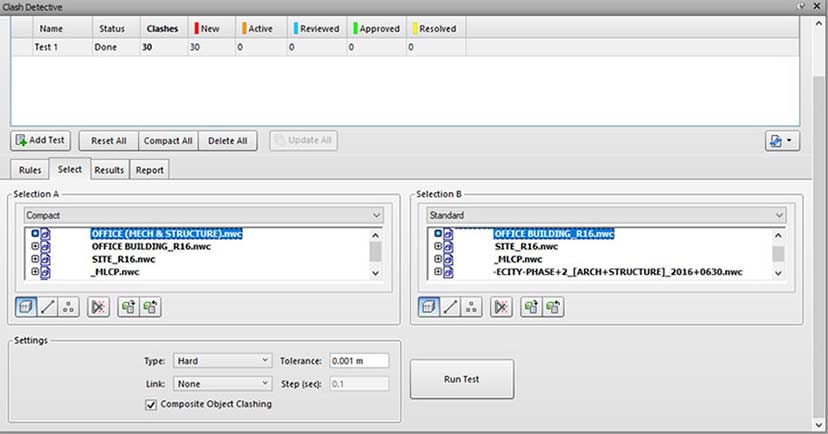 Selecting two different discipline models
STEP 4: Running the clash test in Navisworks produces a list of clashes between the two independent models, along with detailed information about each clash.
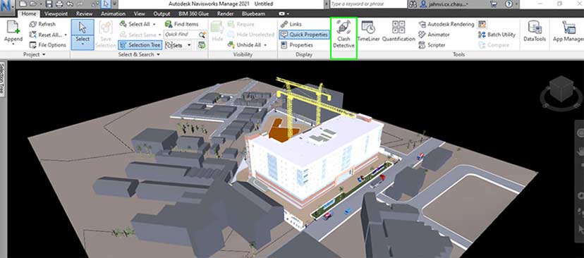 Clash detection process initiated
STEP 5: Users can select the details to include in the clash report by checking various report options. By clicking the “Write report” option, a detailed clash report is generated for the two 3D models.
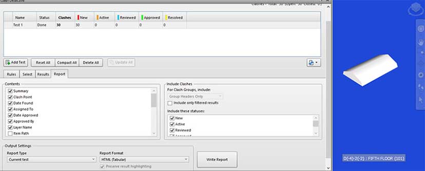 Finalizing the details to be included in clash report
BIM-based clash detection plays a crucial role in modern construction. As global projects become increasingly complex across Architecture, Structural, and MEPF disciplines, the need to complete projects on time and within budget makes clash detection essential for improving coordination, and ensuring accurate BOMs, BOQs, and GFC drawings.
The use of a Common Data Environment (CDE) and clash-free generative design is gaining popularity in complex projects. As technology evolves, the adoption of advanced BIM tools with coordinated, interference-free 3D models will become standard practice in the industry.
BIM-based clash detection and resolution will remain a critical process during the pre-construction phase for multiple stakeholders. Having a coordinated, multi-disciplinary, and clash-free 3D model readily available ensures significant cost and time savings in the digital space. Eliminating clashes early in the design stage using automation scripts will greatly reduce design, procurement, fabrication, and installation time and costs.
As the world shifts toward greater sustainability and more efficient use of energy and resources, clash detection and the pre-construction resolution of clashes will become mandatory rather than optional.
You may also like
From 2D to 3D: Why Architects are Switching to BIM Modeling
10 Essential Best Practices for BIM in MEP Engineering
How 3D Scan to Revit Can Solve As-Built Modeling Challenges