
IFC and shop drawings extracted from clash-free 3D BIM models streamline construction projects by illustrating finer technicalities about design objects, ensuring seamless fabrication and installation.
Construction drawings from 3D BIM have changed the game in execution of construction projects. With the chances of drawing errors coming up during project progress almost eliminated, project delays and cost overshoots have significantly reduced. Contractors and fabricators have been able to cut down on rework, delays and installation issues significantly using detailed IFC and shop drawings based on 3D BIM.
IFC and shop drawings extracted from clash-free 3D BIM models hold the key for contractors and fabricators to achieve error-free and streamlined fabrication and installation. With coordinated and clash-free 3D BIM models, contractors can extract accurate, interference-free, and detailed shop and IFC drawings. These drawings include detailed fabrication drawings for columns and beams, MEP components, structural elevation, floor plans, and cross-sectional 2D deliverables.
Adopting BIM at the early stages of construction, enables contractors to gain a smooth and hassle-free fabrication and installation.

This article discusses the issues with traditional and CAD based 2D design, and how accurate IFC and Shop drawing generation can solve them.
Get accurate IFC and shop drawing extraction for your construction projects.
KNOW OUR MEP SHOP Drawings OFFERINGS »Traditional 2D drawings produced by hand or CAD software are often error-ridden and incomplete. Error-ridden drawings are a consequence of silos or uncoordinated workflows. Supporting the pre-construction stage design planning with coordinated and interference-free 3D models takes the guesswork out of the equation.
IFC and shop drawings extracted from parametric 3D models are highly accurate. Revit® families further enrich the model with real-world component modeling. These highly relevant and coordinated drawings, reduce ambiguities in the installation stage, speeding up the construction process.
Revit structural model with LOD 450 for office building saves project costs
A leading pre-cast manufacturing firm needed a Revit model with LOD 450 for an office building in India. The team at Hitech CADD Services created a clash-free 3D Revit model and also delivered a full sheet-up.
The coordinated and accurate documentation with precise shop drawings helped the client speed up the construction process and save on project costs.
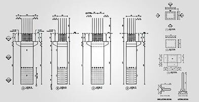
Design errors and onsite rework set a heavy toll on contractors as they lead to project delays and cost overshoots. Uncoordinated 2D drawings do not show an accurate count of the quantity of materials required, leading to rework.
IFC and shop drawings extracted from 3D Revit models overcomes these flaws, leading to minimal rework and significant time savings. Extracting shop drawings for HVAC, electrical, and plumbing components with accurate BOQs and BOMs helps contractors gain an accurate count and cost of material. With detailed drawings, contractors can zero in on unique systems, features, and MEP components for improved clarification.
BIM modeling with LOD 400 reduces rework for residential building, USA
An architectural engineering firm from the US outsourced its requirements to Hitech CADD Services for MEP BIM services for residential building construction. PDF files with mark-up drawings were provided as input by the client. The team at Hitech CADD Services developed a coordinated MEP 3D model at LOD 400 and extracted construction drawings. The final deliverables provided to the client enabled flawless fabrication and installation of MEP components. It also reduced project rework, saving time and costs.
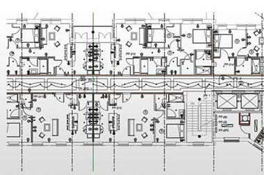
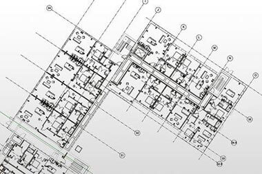
Lack of visualization leads to increase in RFIs and change orders in the construction stage and can lead to project delays, and thousands of dollars in cost overruns. Enhanced visualization with information-rich 3D Revit models in the early design stage reduces expensive change orders in the construction stage.
With greater clarity and error-free representations, contractors can extract accurate and coordinated IFC and shop drawings, reducing costly change orders and cost overruns.
The university of Colorado, Denver health sciences project observed a reduction of more than 70% in RFI’s during the project foundation phase.
BIM clash detection saves $7M for international airport, Middle East
A general contracting company from Muscat, Oman outsourced its MEP clash detection requirements to Hitech CADD Services for airport construction. With IFC drawings & architectural and structural BIM models provided as input, the team began BIM modeling work.
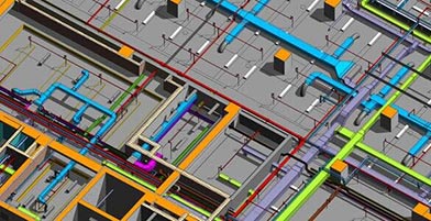
A clash-free and coordinated 3D MEP model with LOD 400 and clash detection reports were created. The final deliverables enabled the client to save $7 million within 6 months. With zero change orders and reduced field conflicts, the terminal became operational with 100% installation of MEP systems.
Read Complete Case Study »Get clash-free 3D Revit models with complete documentation set.
Read about our architectural BIM offerings »Clash visualization, identification, and resolution between various trades in the pre-construction stage is the base of powerful BIM modeling. Getting various 3D models, such as architecture, structure, and MEPF to coexist in a single coordinated model is what drives contractors to adopt BIM-based drawings.
Clash-free and coordinated IFC and shop drawings generated from clash-free 3D models lead to synchronized component functioning, highly accurate prefabrication, and flawless onsite installation.
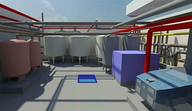
3D clash detection enables better decision making for a plant room, Europe
BIM consultants from Europe outsourced their requirements for 3D modeling and clash detection to Hitech CADD Services. With 2D Pdf files and details of MEP equipment provided as input, the team had to produce the deliverables. Navigating around challenges, the team built a coordinated and clash-free 3D Revit model that led to proactive clash detection, informed decision making, and cost savings.

Traditional designing in 2D, be it CAD or hand-drawn sketches, does not incorporate or reinforce shop or IFC drawings with industry standards.
Coordinated 3D BIM models authored in parametric software like Revit, and clash checked in Navisworks® are enriched with global designing standards. Informative annotations, mark-ups, dimensions, conventions, specifications, and other parameters incorporated in the 3D model help contractors align their drawings with project requirements.
IFC and shop drawings extracted from coordinated BIM models reinforced with global standards, ensure an error-free fabrication and installation process.
An RFI can cost $1000 to analyze and respond, and it could take 7-10 days or more to receive a response. Based on a study, more than 20% of RFIs are not answered.
Shop drawings are produced by contractors, sub-contractors, and fabricators, while IFC or Issued-for-Construction drawings are provided by the client or consultant to the project contractor. Model-extracted shop drawings and IFC drawings issued by a consultant usually facilitate greater prefabrication accuracy through greater information detail.
These IFC and shop drawings provide a finer understanding of component design, BOQ and BOM. Fabricators in offsite locations can use the right set and quantity of materials to manufacture building components. This leads to improved material planning and a reduction in onsite material waste.
Based on a study, 54% of contractors indicate the shortage of at least one construction material.
To enhance productivity and construction quality, openBIM was introduced to the AEC fraternity. Maximizing the effect of BIM by generating IFC-based 2D drawings automatically in an openBIM application can improve efficiency and reduce duplication. With the AEC industry being large and complex, a variety of software is used to handle and process information. Information incompatibility and errors can occur during the data exchange or usage process.
OpenBIM is a concept that centers its capabilities on software independence to ensure interoperability and interchangeability. IFC was a neutral format to facilitate BIM data exchange through relationships between objects and their attributes. Developing a module that incorporates the need to build steel reinforcement construction drawings, process schedules precisely through structural models, and reference architecture as an object could optimize the IFC criterion.
Understanding advanced processes and tools in the construction industry can be challenging. Misinterpreted components can lead to various design and construction errors. Leveraging a greater understanding of details through IFC and shop drawings requires BIM-based 2D specialists with extensive extraction skills, and experience.
A well-set BIM service company can deliver accurate and detailed drawings to facilitate error-free and flawless installations. Extracting model-based IFC and shop drawings with precise floor plans, elevations, building, wall and detail sections, enlarged views etc. simplifies fabrication and installation for construction projects.
You may also like
From 2D to 3D: Why Architects are Switching to BIM Modeling
10 Essential Best Practices for BIM in MEP Engineering
How 3D Scan to Revit Can Solve As-Built Modeling Challenges
DXF Files in SolidWorks: How to Import and Export Them