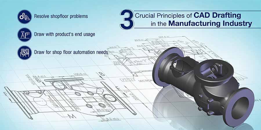
CAD drafting boosts precision with AutoCAD, Inventor, and SolidWorks. Strategic drafting bridges design and production, while automation-ready CAD streamlines workflows for smart factories. These principles ensure accuracy, efficiency, and future-ready manufacturing.
Table of Contents
CAD drafting in manufacturing using software like AutoCAD, Inventor, and SolidWorks has redefined how products are designed, developed, and produced. These powerful tools enable engineers to create precise 2D drawings and 3D models that serve as the foundation for manufacturing processes.
However, the manufacturing sector faces increasing challenges – rapid design changes, complex product requirements, and demanding production schedules. While CAD applications offer sophisticated features, their effective implementation relies on three fundamental principles or rules of drafting and drawing creation.
These principles for efficient CAD drafting techniques for designers, ensure that CAD drawings effectively bridge the gap between design intent and shop floor execution, whether working in AutoCAD for detailed 2D documentation, using Inventor for parametric 3D modeling, or leveraging SolidWorks for complex assemblies.
The following are the 3 principles that ensure success in CAD drafting for manufacturing:

The primary challenge in manufacturing lies in bridging the gap between idealized designs and real-world production capabilities. Design engineers using AutoCAD, SolidWorks, or Inventor often create theoretically perfect models of a mechanical component or equipment drawing, while shop floor realities present different constraints. This disconnects frequently leads to production delays, material waste, and unnecessary iterations
Modern CAD drafting addresses these challenges with comprehensive documentation, including:
Strategic CAD drafting provides a unified communication platform between design and production teams, streamlining design handoffs and reducing confusion. A single master CAD file, produced by this process, serves as a cross-departmental reference, thus minimizing production errors and revision cycles. Ultimately, strategic CAD drafting enhances manufacturing efficiency.
Explore how CAD is transforming every stage modern manufacturing .
View Infographic »Transforming Concept Sketches into Detailed CAD Engineering for Retail Furniture
A UK-based retail furniture designer and manufacturer sought to convert hand-drawn concept sketches into precise CAD models and manufacturing drawings for fitting room furniture. The client required accurate interpretation of design intent to ensure seamless integration with existing store fixtures.
The team at Hitech CADD Services, made of experienced SolidWorks drafters collaborated closely with the client to understand their design requirements. They developed 3D models and rendered images, facilitating design approvals and clarifications. Subsequently, detailed 2D manufacturing drawings were created, adhering to the client’s standards and ensuring manufacturability.
The final deliverables led to:
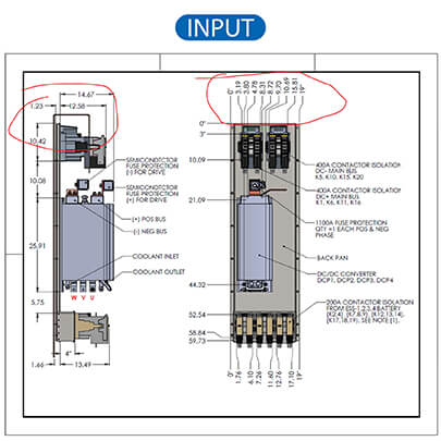
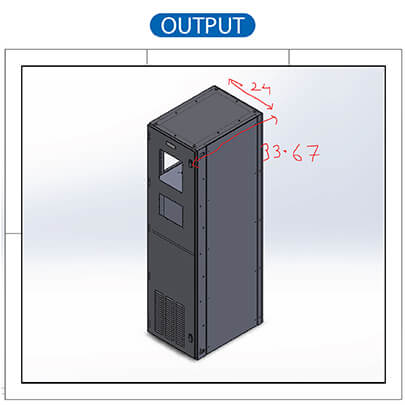

One of the most critical issues in manufacturing occurs when product usage requirements get lost in translation between design approval and CAD production drawings. This disconnects leads to multiple revision cycles, manufacturing delays, and extended time-to-market, particularly when working with complex designs in SolidWorks, Inventor, or AutoCAD.
Understanding product usage parameters from the outset enables CAD designers to create more accurate and efficient drawings. Following are some key considerations for this:
When these are clear to CAD engineers, they can develop detailed part drawings that reduce design revisions and accelerate the product development cycle while ensuring manufacturing accuracy.
Successful implementation of this approach requires a systematic approach to CAD drafting that considers both design intent and manufacturing requirements. Here’s a breakdown of the CAD drawing best practices:
Design automation helps product-centric CAD drafting by streamlining the creation of manufacturing-ready designs across different product variants. Using tools like DriveWorks integrated with SolidWorks, designers can rapidly generate accurate drawings that maintain design intent while incorporating manufacturing specifications.
Detail your drawings with the best!
HAVE A WORD WITH US »Design Automation Enhances Efficiency for European Stairlift Manufacturer
A European stairlift manufacturer collaborated with Hitech CADD Services to automate their design processes. The client aimed to reduce engineering lead times and minimize errors in production and installation by automating the generation of 3D CAD models and fabrication drawings for stairlifts and rail designs.
Hitech CADD Services’s team analyzed the client’s existing AutoCAD drawings and utilized SolidWorks APIs to migrate legacy CAD data, ensuring critical functionalities remained intact. They developed custom features, macros, and tools using C++, SQL, Java, and .NET to automate the creation of standard 3D CAD models, fabrication, and general arrangement drawings. This automation enabled rapid ‘what-if’ simulations by adjusting design parameters digitally, facilitating quick identification of design trade-offs.
The implementation of design automation led to:
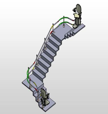 Stairlift 3D Model
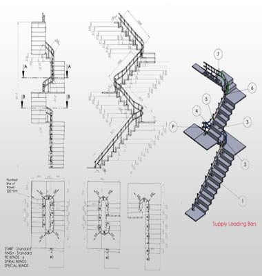 Stairlift Manufacturing Drawings

The manufacturing industry is stepping into the fourth industrial revolution (Industry 4.0), characterized by smart factories, interconnected systems, and automated processes. This demands advanced digital solutions where every stage, from concept to manufacturing, leverages automation technologies. Modern manufacturing facilities increasingly rely on robotics, smart sensors, and integrated digital systems to maintain competitive advantages.
Modern CAD systems (AutoCAD, SolidWorks, and Inventor) serve as the fundamental bridge between design intent and automated manufacturing processes:
The implementation of automation-ready CAD practices in manufacturing environments yields substantial operational advantages that extend throughout the production pipeline. When CAD systems are properly configured for automation, they enable seamless digital workflows that enhance production quality through consistent data transfer and standardized processes.
The integration with CAM systems allows for optimized tool path generation, resulting in reduced tool wear and extended equipment life spans. Manufacturing cycle times are dramatically shortened as automated processes eliminate manual data entry, reduce setup times, and enable rapid changeovers between different product variants.
Automation-ready CAD systems facilitate better quality control through integrated metrology, enabling real-time comparison between as-designed and as-built components.
Design Automation for Hollow Metal Door Manufacturer
A USA-based manufacturer of hollow metal doors and frames sought to streamline their design process. The client required automation of 3D CAD modeling and manufacturing drawings to reduce engineering lead times and improve response to customer inquiries.
Hitech CADD Services collaborated with the client’s design engineers to implement a custom door configurator using DriveWorks Solo. This solution automated the generation of 3D models and manufacturing drawings, integrating a SQL database for efficient design data management and minimizing errors associated with manual customization.
The final deliverables led to:
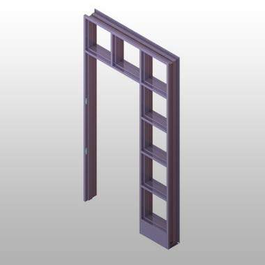 Metal Frame 3D Modeling
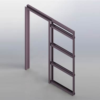 Panel 3D Modeling in SolidWorks
How Engineers & Architects Gain from 3D CAD Outsourcing
Read Now! »CAD platforms have transformed manufacturing by enabling the creation of precise 3D models, which streamlined design processes, reduced errors, and facilitated virtual prototyping. CAD platforms integrate with CAM systems for automated production, optimizing manufacturing efficiency and accuracy. Learn about different CAD platforms and how they changed manufacturing industry practices.
CAD drafting now, is developing beyond traditional design tools into an integral part of the digital manufacturing ecosystem. As Industry 4.0 technologies mature, CAD systems like AutoCAD, SolidWorks, and Inventor are becoming more deeply integrated with artificial intelligence and machine learning capabilities, enabling predictive design optimization and automated error detection.
The future promises seamless integration between CAD systems and emerging technologies, such as augmented reality for real-time design visualization, digital twins for virtual commissioning, and generative design algorithms for optimal part creation. Cloud-based CAD platforms will enhance collaboration across global manufacturing teams, enabling real-time design reviews and instant feedback from shop floor to design office.
CAD systems will increasingly incorporate sustainability parameters, allowing designers to optimize material usage and energy efficiency during the design phase.
These principles for CAD drafting remain contemporary even though CAD tools are ever evolving. Today, as the concept of CAD for Industry 4.0 with connected devices and 3D printing emerge rapidly, these three principles of CAD become even more critical. As both these trends are based on digitization, developing comprehensive CAD models and drawings for your legacy designs is the foundation.
These principles are rules to avoid revisiting CAD drawings for corrections, especially when the industry landscape is transforming. Going forward, these principles also work towards adapting to the changing requirements and preparing engineering firms for the coming times.
Precision in CAD drafting is crucial for manufacturing because it ensures that parts are produced with the correct dimensions and tolerances. This minimizes errors, reduces waste, and ensures that components fit together correctly during assembly. Precise drawings also facilitate accurate cost estimation and procurement of materials.
CAD drawings allow manufacturers to visualize and analyze designs before production begins. This helps identify potential problems, such as interference between parts, difficult assembly sequences, or areas of stress. By addressing these issues in the design phase, costly rework and delays in production can be avoided.
A CAD drawing for manufacturing should include detailed dimensions and tolerances, material specifications, surface finish requirements, geometric dimensioning and tolerances (GD&T) as well as notes and special instructions.
CAD drawings serve as the primary communication tool between designers, engineers, and shop floor personnel. They provide a clear and concise visual representation of the product, eliminating ambiguity and ensuring everyone is working from the same information. This improves communication, reduces errors, and promotes efficient production.
Product usage heavily influences CAD design principles. Designers must consider how the product will be used, its environment, user interactions, and potential stresses to ensure functionality, durability, and safety. For example, a product designed for outdoor use will require different materials and design considerations than one intended for indoor use.
Designing with usage in mind ensures that the product meets the needs of the end-user. It leads to products that are functional, safe, durable, and user-friendly. Ignoring usage can result in products that are difficult to use, prone to failure, or even dangerous.
Designers can minimize revisions by thoroughly understanding the design requirements, conducting design reviews, using simulation and analysis tools and following drafting standards.
CAD data can be directly used to program CNC machines, robots, and other automated systems. This eliminates the need for manual data entry, reduces errors, and speeds up production. CAD/CAM software facilitates a seamless flow of information from design to manufacturing.
CAD-CAM systems are central to modern manufacturing. They streamline the entire production process from design and prototyping to machining and quality control. This integration improves efficiency, reduces lead times, and enables the production of complex parts with high precision.
Automation reduces the potential for human error in creating and interpreting drawings. Automated tools can check for inconsistencies, ensure adherence to standards, and generate tool paths directly from the CAD model, leading to more accurate and reliable manufacturing drawings.
CAD drafting addresses several challenges in manufacturing such as reducing design errors, improving communication, increasing efficiency, enabling complex designs and facilitating innovation.
You may also like
From 2D to 3D: Why Architects are Switching to BIM Modeling
10 Essential Best Practices for BIM in MEP Engineering
How 3D Scan to Revit Can Solve As-Built Modeling Challenges
DXF Files in SolidWorks: How to Import and Export Them