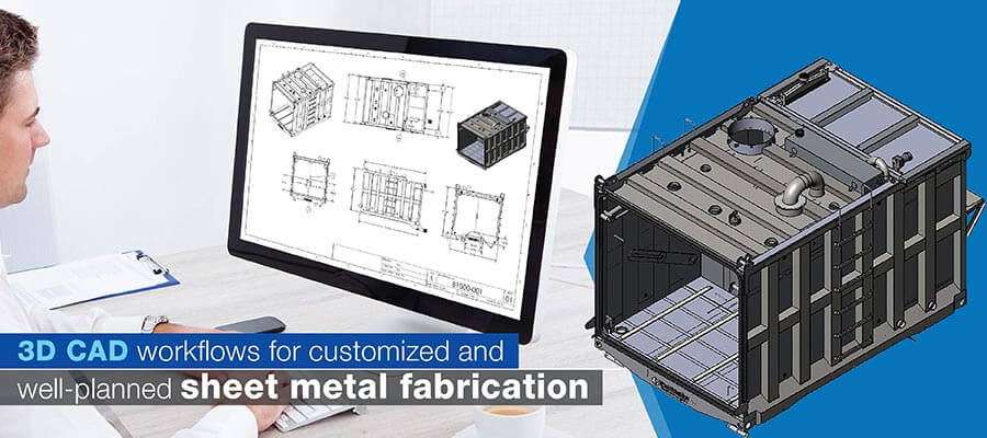
Legacy design methods for building product fabrication are often slow and inaccurate. 3D CAD modeling transforms this process by speeding up engineering lead times, offering detailed visualization, and enabling direct manufacturing. This modern approach allows sheet metal fabricators to create precise, personalized designs efficiently, reducing reworks and costs. By adopting 3D CAD modeling, manufacturers can improve communication between design and production teams, ensuring a seamless and accurate fabrication process.
Table of Contents
In today’s customer-driven market, sheet metal product fabrication demands bespoke design and a tailored approach. Whether it’s a door frame, an enclosure, ducts, or panels, customers expect a 360-degree visualization of the final product before placing an order. Traditional 2D drawings often fall short in clearly communicating design intent and hinder quick design customization, leading to reworks, additional costs, and project delays.
The adoption of 3D CAD modeling has revolutionized sheet metal fabrication, especially for engineers, fabricators, product designers, and manufacturers. A comprehensive 3D sheet metal modeling platform ensures seamless design handoff between designers and manufacturers, enhancing precision, efficiency, and communication. This article explores why 3D CAD modeling is essential for modern sheet metal product fabrication, addressing specific challenges, key features, and the numerous benefits it offers.
3D CAD modeling involves the creation of a virtual 3D representation of sheet metal parts and assemblies using specialized CAD software. It allows designers to accurately model complex sheet metal geometries, including bends, folds and holes, and simulate their manufacturing processes.
This helps identify and rectify potential design flaws before production, saving time and costs.
Sheet metal fabrication has undergone a remarkable transformation from its origins in manual cutting and shaping. Traditional methods are often labor intensive and error-prone, leading to costly mistakes and material wastage.
The advent of 3D CAD modeling has revolutionized this process, providing a more efficient, accurate and cost-effective solution. With 3D CAD, the entire fabrication process can be meticulously planned and visualized, minimizing errors and streamlining production.
For years, sheet metal fabrication was guided by 2D drawings, which, although effective to an extent, presented numerous challenges. Here are some of the core issues faced by engineers and fabricators when relying on 2D drawings:
Switching to 3D CAD modeling can help solve these issues and bring numerous other benefits to the sheet metal product fabrication process.
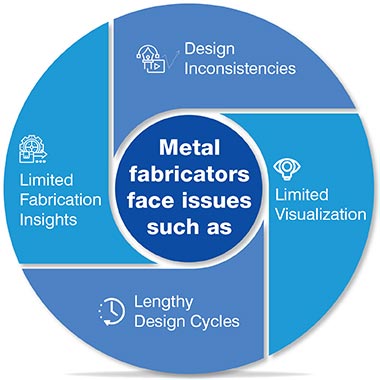
3D CAD modeling has emerged as a game changer for sheet metal fabrication, particularly for engineers, manufacturers, and product designers. Here’s how 3D CAD can help overcome the limitations of 2D drawings:
Establish seamless workflows across stakeholders.
Hire a 3D CAD expert »For sheet metal fabricators and product designers focusing on building products such as HVAC systems, roofing, and cladding, 3D CAD modeling offers numerous benefits:
3D CAD modeling integrates DFM (Design for Manufacturability) guidelines, which help engineers design products that are not only functional but also easy and cost-effective to fabricate. This reduces the need for design iterations, saving both time and material costs.
CAD tools like SolidWorks & Inventor have in-built features for DFM guidelines that allow auto-calculations. In the absence of such automated suggestions and red flags, the designer must do the calculations manually, which are often error prone.
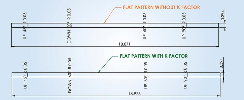
Let’s take the example of bending – a common feature of any sheet metal component. While designing bends, the designer must consider accurate K-factor to reduce the spring back effect (or band back). Values for K-factor are different for different materials. Advanced CAD software has these values as an in-built feature for different materials such as steel, copper, brass, and aluminum.
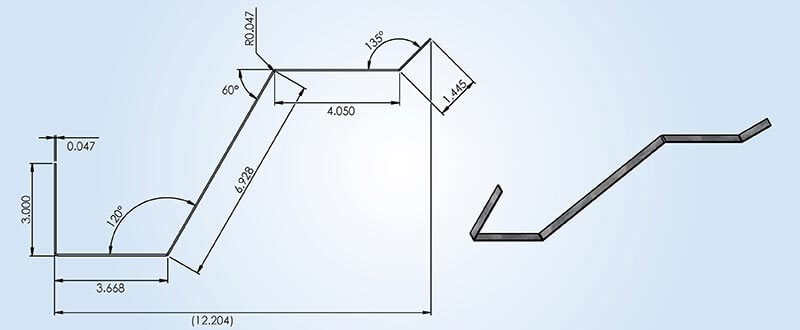
With the help of a 3D model, the designer can create accurate flat patterns that help generate DXFs for cutting and cost calculations.
3D CAD software can automatically generate flat patterns from 3D models, allowing sheet metal fabricators to cut and fold materials with higher accuracy. This minimizes material waste and reduces the likelihood of errors during fabrication.
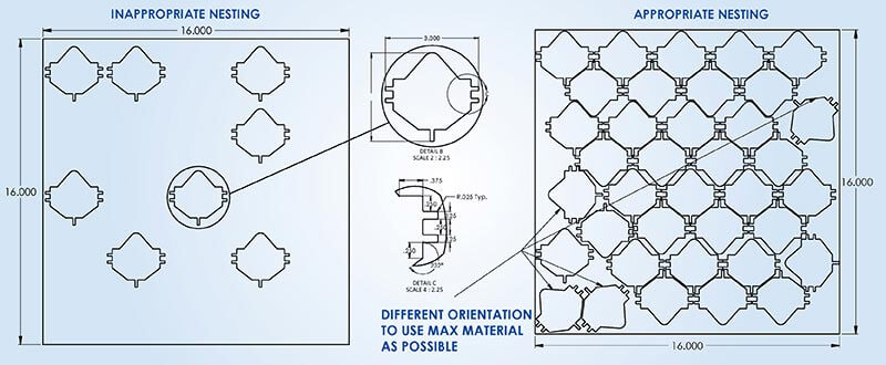
Nesting is the process of arranging flat patterns in an optimal layout to maximize material utilization. With 3D CAD, fabricators can automate nesting, reducing scrap and saving costs in raw materials.
Nesting makes optimized use of raw material in sheet metal component manufacturing and helps reduce the scrap. It obeys the following rules:
Following these rules becomes easier for the design engineer with 3D design models.
3D CAD modeling simplifies the assembly process by integrating DFMA (Design for Manufacturing and Assembly) principles. This reduces assembly time and cost while improving product quality, ensuring that parts fit together seamlessly during final assembly.
With DFMA guidelines, the designer can control the number of components in 3D assembly model. Modern CAD tools provide quick clearance checks along with DFMA rules. CAD platforms show suggestions to combine different parts and reduce the total number of components that come together to form the assembly.
Overcome Sheet Metal Fabrication Challenges with Detailed Shop Drawings
Struggling with project delays and costly errors in sheet metal fabrication?
Discover how to:
Start optimizing your sheet metal fabrication process!
Download your copy Today!Sheet metal 2D drawings with all technical details can be directly generated from highly precise 3D CAD models. These models have all technical details with geometric dimensions and notes to minimize manufacturing errors.
Since detailed 2D drawings are derived from the parent 3D models, any changes in the models are reflected in the drawings. This improves communication between the shop floor, purchasing and quality teams. 3D CAD models of sheet metal parts also have accurate BOMs that help calculate the required material quantity to maintain inventory levels.
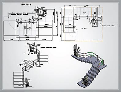
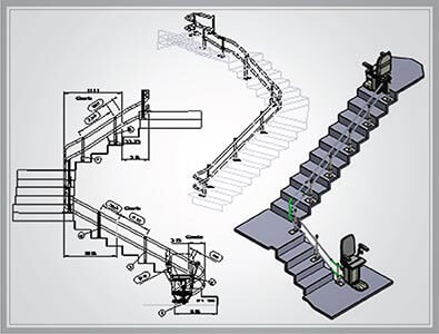
Success Story: 3D Modeling & Fabrication Drawing for Stair Lifts Manufacturer
A European stairlifts manufacturer faced challenges managing orders with specialized bends resulting in lengthy engineering lead times. Hitech CADD Services’ engineers translated the legacy design drawings to SolidWorks models and generated APIs to customize the designs. Fabrication shop drawings were generated later as and when needed. This ensured seamless and faster design data exchange between design teams and the shop floor.
For sheet metal fabricators and engineers, adhering to DFM (Design for Manufacturability) guidelines is crucial to reducing production costs and avoiding design iterations. By using 3D CAD, designers can implement DFM principles from the start, allowing for more manufacturable designs. Case studies show that companies using 3D CAD have reduced production time by up to 30% while cutting material costs by 20%.
A flat pattern is a 2D representation of a 3D sheet metal part that shows the precise layout for cutting and folding. 3D CAD simplifies the creation of flat patterns, automatically generating them from 3D models. This ensures that the flat pattern aligns perfectly with the folded product, reducing the chances of cutting or bending errors during fabrication.
In sheet metal fabrication, maximizing material usage is critical for reducing waste and costs. Nesting in 3D CAD helps arrange multiple flat patterns on a sheet of metal in the most efficient layout. This reduces scrap material, making the production process more sustainable and cost-effective.
Using DFMA principles in 3D CAD, engineers can design products that are easier to manufacture and assemble. By integrating manufacturing and assembly considerations from the beginning, the overall product design is optimized for efficiency. This leads to shorter production times, reduced costs, and fewer assembly errors.
For sheet metal fabricators, accurate 2D technical drawings are essential for ensuring the product is fabricated to the right specifications. 3D CAD automatically generates these drawings, along with a detailed BOM (Bill of Materials), which lists all necessary materials. This ensures that the fabrication process runs smoothly, without the need for manual measurements or guesswork.
Modern CAD tools have a lot more to offer, in addition to seamless communication between designers and manufacturers. They enhance design visualization and designer’s efficiency by connecting nodes between sales and manufacturing.
Visualization and personalization are the key requirements to win customers. 3D CAD enables 360-degree visualization with rendering and walkthrough of personalized designs of building products.
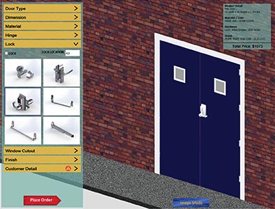
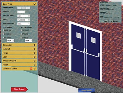
3D visual configurator allows for configuring the designs in the form of rules and specifications. For instance, a customer can select the doorframe directly from the portal and define his exact requirements. Once the design is finalized, 3D CAD enables 360-degree visualization with rendering and walkthrough of personalized designs of building products. They receive a design quote and delivery time immediately, even in absence of sales personnel.
Advanced 3D CAD modeling platforms have made direct manufacturing possible by feeding DXFs to machines used for cutting metal sheets. This means that there is zero human interference during machining and errors are minimized.
Additionally, MBD features in 3D modeling improve the value chain and collaboration performance from sales to manufacturing. The designer can embed all product information into a single 3D CAD model that serves as a single source of truth across the value chain.
Success Story: Design Automation for Hollow Metal Doors & Frames Manufacturer
For a US-based door manufacturer, the Hitech CADD Services automation team developed a door configurator using SolidWorks and DriveWorks to achieve a faster design cycle. It reduced total time to respond to a customer inquiry and also brought down the design cycle time by 70%.
The future of sheet metal fabrication is directed toward more efficiency, higher precision, and a genuine commitment to sustainability. We’re seeing a clear shift towards automation and robotics to handle those intricate, complex tasks, which minimizes errors and significantly boosts productivity.
Additive manufacturing, or 3D printing, is also making waves, enabling us to create geometries that are simply impossible with traditional methods. There is also a growing emphasis on greener practices – using recycled materials, adopting energy-efficient processes – all to reduce our environmental footprint.
These advancements won’t just enhance the capabilities of 3D CAD, they’ll boost innovation and efficiency in sheet metal fabrication. Manufacturers who embrace these trends are the ones who’ll be leading the charge in the years to come.
Using 3D CAD provides enhanced visualization, allowing engineers, fabricators, and designers to see a complete, interactive model of the product. This ensures better accuracy and precision compared to 2D drawings, which are harder to interpret.
3D CAD also integrates seamlessly with CAM systems, allowing for automated cutting, bending, and assembly processes. By using 3D CAD, collaboration is improved across teams, reducing miscommunication, and making it easier to spot errors early. Additionally, simulations and stress analyses can be conducted, helping detect issues before fabrication begins.
3D CAD reduces material waste primarily through optimized nesting and precise flat pattern generation. Nesting algorithms arrange flat patterns on sheet metal in a way that maximizes material usage, leaving minimal gaps and reducing scrap.
3D CAD also ensures flat patterns are accurate, eliminating errors in cutting and bending. This automation reduces the need for manual interventions, lowering the chances of mistakes. Overall, 3D CAD helps save material costs, while making the production process more sustainable by reducing waste.
3D CAD significantly enhances communication between design and fabrication teams by providing a unified, visually rich platform where all stakeholders can interact with the same model. Unlike 2D drawings, which may be subject to varying interpretations, 3D CAD models offer a complete, accurate representation of the product.
Teams can collaborate in real time, making modifications that are immediately visible to everyone involved. This ensures that designers, engineers, and fabricators are all on the same page, reducing the likelihood of misinterpretations and production errors.
DFMA (Design for Manufacturing and Assembly) ensures that products are designed to be both manufacturable and easy to assemble. In 3D CAD, DFMA is crucial as it allows engineers and product designers to optimize their designs for efficient fabrication processes.
It reduces part complexity, cuts down on the number of components, and ensures that the final product can be assembled quickly and cost-effectively. By adhering to DFMA principles, 3D CAD helps streamline production, reduces waste, and lowers both material and labor costs, ensuring higher efficiency.
In today’s fast-paced manufacturing landscape, the shift from 2D drawings to 3D CAD modeling is crucial. 3D CAD enhances precision, efficiency, and material savings, helping engineers, fabricators, and manufacturers optimize production processes. As the industry evolves, 3D CAD will continue to shape the future of sheet metal product fabrication.
With increasing demand for customization and faster delivery, 3D CAD modeling enables sheet metal fabricators to reduce design inefficiencies and control material waste. It enhances collaboration, ensures accuracy in shop drawings, and automates repetitive tasks, boosting productivity and allowing manufacturers to focus on delivering innovative, customer-centric solutions.
You may also like
BIM-Based MEP Coordination for Multi-Trade Collaboration
How AI and ML are Shaping the Future of Scan to BIM
Cabinet Shop Drawings: A Detailed Guide